B&O Tech: What is “ABL”?

Header info #1 for full disclosure: I’ve been given the green light from the communications department at Bang & Olufsen to write some articles describing some of the more technical aspects of B&O loudspeakers here on my own blog site. This is the first posting in what will be a series of articles.

Header info #2 for fuller disclosure: This particular posting will look familiar to some forum people at www.beoworld.org, since I wrote the original version of this as a response to one of the questions on their site. However, I’ve beefed up the response a little – so if you’ve come here from beoworld, there is only a little new information in here.

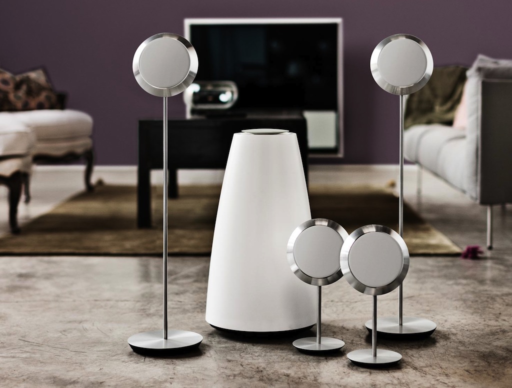
Almost all loudspeakers made by Bang & Olufsen include Adaptive Bass Linearisation or ABL. This includes not only our “stand alone” loudspeakers (the BeoLab series) but also our iPod docks and our televisions. The only exceptions at the moment are our passive loudspeakers, headphones, and the BeoLab 5.

There is no one technical definition for ABL, since it is in continual evolution – in fact it (almost) changes from product to product, as we learn more and as different products require different algorithms. Speaking very broadly, however, we could say that it reduces the low frequency content sent to the loudspeaker driver(s) (i.e. the woofer) when the loudspeaker is asked to play loudly – but even this is partially inaccurate.

It is important to note that it is not the case that this replaces a “loudness function” which may (or may not) be equalising for Equal Loudness Contours (sometimes called “Fletcher-Munson Curves”). However, since (generally) the bass is pulled back when things get loud, it is easy to assume this to be true.

When we are doing the sound design for a loudspeaker (which is based both on measurements and listening), we make sure that we are operating at a listening level that is well within the linear behaviour of the loudspeaker and its components. (To be more precise, when I’m doing the sound design, I typically use a standard-ish playback level where -20 dB FS full-band pink noise results in something like 70 dB (C) at the listening position (sometimes I use 75 dB (A) – but, depending on the amount of low end in the loudspeaker, this might result in the same volume setting).)

This means that

  • the drivers (i.e. the woofer and tweeter) aren’t being asked to move too far (in and out)
  • the amplifier is nowhere near clipping
  • the power supply is well within its limits, and
  • nothing (not the power supply, the amplifiers, or the voice coils) is getting so hot that the loudspeaker’s behaviour is altered.

This is what is meant by “linear” – it’s fancy word for “predictable”, (Not to mention the fact that if we were listening to loudspeakers at high levels all the time, we would get increasingly bad at our jobs due to hearing loss.)

So, we do the tuning at that low-ish listening level where we know things are behaving – remember that we always do it at the same calibrated level every time for every loudspeaker so that we don’t change sound design balance due to shifts associated with equal loudness contours. (If you tune a loudspeaker when it’s playing loudly, you’ll wind up with a loudspeaker with less bass than if you tuned it quietly. This is because you’re automatically compensating for differences in your own hearing at different listening levels.)

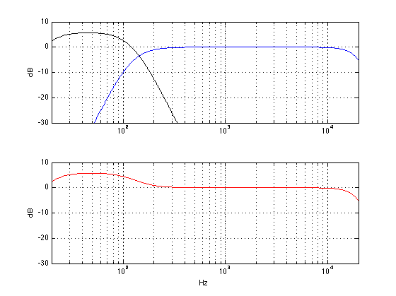
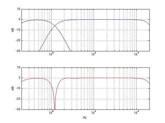
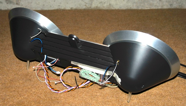
Once that tuning is done, then we go back to the measurements to see where things will fall apart. For example, in order to compensate for the relatively small cabinet behind the woofer(s) in the BeoSound 8 / BeoPlay A8, we increase the amount of bass that we send to the amplifiers for the woofers as part of the sound design. If we just left that bass boost in when you turn up the volume, the poor speaker would go up in smoke – or at least sound very bad. This could be because

  • the woofer is being pushed/pulled beyond its limits, or
  • because the amplifier clips or
  • the power supply runs out of steam or
  • something else.

(Note that BeoSound 8’s do not actually run on steam – but they do contain the magic smoke that keeps all audio gear functioning properly.) So, we put the loudspeaker in a small torture chamber (it’s about the size of a medium-sized clothes closet), put on some dance music (or some slightly more-boring modified pink noise) and turn up the volume… While that’s playing, we’re continually monitoring the signal that we’re sending to the loudspeaker, the driver excursion, the demands on the electronics (i.e. the amp’s, DAC’s, power supply, etc) and the temperature of various components in the loudspeaker, along with a bunch of other parameters…

beosound_8_last_prototype
One of the last BeoSound 8 prototypes. The orange/black wires connect directly to the woofers. The purple/white wires connect directly to the tweeters (at this stage of development, we are still using external amplifiers). Most of the other wires go into thermal sensors inside the device to see how hot things are getting inside. Some of these thermal sensors are actually in the final product that the customer buys. Some are just for development purposes and are not in the final product.

Armed with that information, we are able to “know” how those parameters behave with respect to the characteristics of the music that is being played (i.e. how loud it is, in various frequency bands, for how long, in both the short term and the long term). This means that, when you play music on the loudspeaker, it “knows”

  • how hot it is at various locations inside,
  • the loudspeaker drivers’ excursions,
  • amplifier demands,
  • power supply demands,
  • and so on. (The actual list varies according to product – these are just some typical examples…)

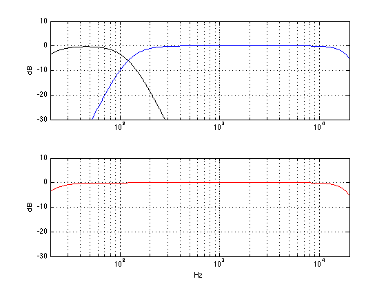
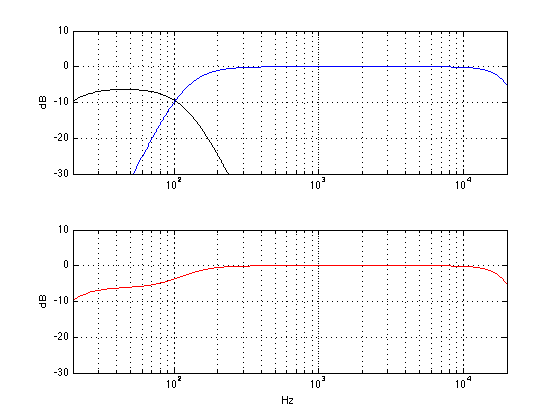
So, when something gets close to a maximum (i.e. the amplifier starts to get too hot, or the woofer is nearing maximum allowable excursion) then SOMETHING will be pulled back.

WHAT is pulled back? It depends on the product and the conditions at the time you’re playing the music. It could be a band of frequencies in the bass region, it could be the level of the woofer. In a worst-case-last-ditch situation, the loudspeaker might even be required to shut itself down to protect itself from you. Of course, there is no guarantee that you cannot destroy the loudspeaker somehow – but we do our best to build in enough protection to cover as many conditions as we can.

HOW is it pulled back (i.e. how quickly and by how much)? That also depends on the product and some decisions we made during the sound design process, as well as what kind of state-of-emergency your loudspeaker is in (some people are very mean to loudspeakers…).

Note that all this is done based on the signals that the loudspeaker is being asked to produce. So it doesn’t know whether you’ve turned up the bass or the volume – it just knows you’re asking it to play this signal right now and what the implications of that demand are on the current conditions (voice coil temperature, for example) This is similar to the fact that the seat belts in my car don’t know why the car is stopping quickly – maybe it’s because I hit the brakes, maybe it’s because I hit a concrete wall – the seat belts just lock up when they’re asked to move too quickly. Your woofer’s voice coil doesn’t know the difference between Eminem and Stravinsky with a bass boost – it just knows it’s hot and it doesn’t want to get hotter.

It’s important to note that some of what I’ve said here is not true for some products. Bang & Olufsen’s analogue loudspeakers cannot have the same amount of “self-knowledge” as the digital loudspeakers because they don’t have the same “processing power”.  However, we make every effort to ensure that you get as much as is possible out of your loudspeaker while still ensuring that you can’t do any permanent damage to it. However, it’s fair to say that, the more recent the model, the closer we are able to get to the maximum limits of the total system for a longer listening period.

Some interesting reading about headphones…

There is something interesting going on in the world of headphones. There are more and more expensive headphones being sold (and, as a result, people appear to be spending more on things like headphone amplifiers and high-resolution recordings…) However, there is some debate (as there has always been since the dawn of the “audio industry” – whatever that is…) whether “expensive” (or “popular”) means “good”.  (Actually if you ask  professionals in the audio industry, I don’t think that they’ll have much of a debate – “expensive” certainly doesn’t mean “good”.)

Quality, or Something Like It” by Stephen Mejias in Stereophile Magazine, May 2013

How do you like your headphone sound: Accurate or bassy?” by Steve Guttenberg on CNET.com

Beat By Dre: The Exclusive Inside Story of How Monster Lost the World” by Sam Biddle on gizmodo.com

Once you’ve read those, you might be interested in some preference work that’s happening at Harman which shows that Bassy is certainly not the preferred choice.

The Relationship between Perception and Measurement of Headphone Sound Quality” by Sean Olive at seanolive.blogspot.com

Makes me wonder how “Bassy” captured 64% of the >100$ headphone market. Must be because conformity is more important than quality…


Bang & Olufsen BeoLab 14 reviews

b-o_beolab_14_0


recordere.dk’s review

“Beolab 14 er et harmonisk sæt, der lyder godt som en samlet enhed. Netop det at det spiller som én samlet enhed, hvor der er kælet for detaljerne, er med til at løfte det flere niveauer op. Bassen virker stram og velafballanceret, men med rigeligt power til effektscenerne i actionfilmene. Mellemtonen virker klar og naturlig, og selv vokaler i highend audio (24-bit) gengives sprødt og realistisk. Diskanten runder det hele fint af i toppen.”


hifi4all.dk’s review

“Beolab 14 sættet lyder ganske enkelt rigtig godt. Der er den rette mængde bas (hvilket man jo egentlig selv bestemmer), et mellemtoneområde, som bare er der uden at gøre væsen af sig, og en diskant som har den rette afrunding mod toppen, hvilket giver god mening sammen med 2,5” enhederne, som per design ikke er konstrueret til ultra høje frekvenser. Og så hænger det hele rigtig godt sammen! Altså det man kalder en homogen gengivelse af musikken.”


Opening a door to a new hobby?

So, I’ve always had a hankering to learn how to make a good crusty French bread. For about 10 years or so, I’ve looked at recipes and even tried a couple, and either ran away in fear, or failed miserably. Then everything changed. I found a video on wimp.com by an entertaining French baker named Vincent Talleu. In 8 minutes and 45 seconds, he edu-tains how to make a simple loaf of french bread. So I watched it and I thought “That doesn’t look too scary – I can do THAT.”

Here’s the video – in case you’re interested…

So, this past Friday night I made the dough – almost exactly the way he shows (I cheated and used dough hooks in a hand mixer – sue me…). Saturday morning I baked the bread in a 5 litre stainless steel pot.

The result looked like this…

first_french_bread 001 (1)


which, I have to say, made me insufferably pleased with myself.

It tasted great – and I wasn’t the only one who thought so. My wife said so, and, just for proof – the kids said it’s the best bread they’ve ever tasted – and they hate EVERYTHING!

So, I sent an email tanking Vincent – and got a nice email back.

Next step: Croissants!

Here endeth the weekend.

Q vs Q

I recently was interviewed by cycling74.com to talk about how I use Max/MSP when I’m doing the sound design for loudspeakers at Bang & Olufsen. I used part of the interview to “complain” gently about the fact that the filtergraph~ object in Max uses Robert Bristow-Johnson’s definition of “Q” without being explicit in stating that it does. (Don’t get me wrong here – I have no issues with RB-J’s definition – I just want to know what I’m using without having to find out for myself…)

Following the interview’s publication on the website, there was a discussion that ensued about this issue. So, I decided to put my money where my mouth is and to find out for sure what the filtergraph~ object is doing.

I could have done this by analysing the 5 coefficients that come out of the object. I decided not to do this – but to actually run an impulse through a biquad~ object to look at the whole filtergraph~ + biquad~ system. So, the patcher I put together to do the analysis looked like this

Screen Shot 2013-09-12 at 11.43.32 AM


Admittedly, it’s a bit quick-and-dirty, but it does the job. If you’re wondering, the only reason the /~ 16 object is there is to make sure I don’t clip the sfrecord~ object.

I kept the centre frequency (fc) at 1 kHz and then did 24 combinations of 6 gains (0.0625, 0.25, 0.5, 2, 4, and 16) and 4 Q’s (1, 2, 4, 16), each producing a single impulse response that I imported into Matlab for analysis.

So, the first question to answer is a rather simple one: Is the filtergraph~ object producing reciprocal peak/dip or constant Q filters when you set its type to “peaknotch”? We can quickly figure this out by putting two filters in series with reciprocal gains and identical centre frequencies and Q’s and looking at the output. Instead, I’ll just put up a plot.

q1


This plot shows 6 filter settings, all with fc=1 kHz and Q = 1. The linear gains are 0.0625, 0.25, 0.5, 2, 4, and 16. As you can see there, the filters with gains of 0.0625 and 16 (or -24 and +24 dB) are symmetrical. Therefore, we can reasonably conclude that we’re using reciprocal peak/dip filters and not constant Q.

Now to the meaty stuff. The question then is “exactly how is Q defined?” If you stay away from definitions of Q that involve damping or the S plane (see here), and we stick with the definitions that people who make filters use (i.e. see here as an example), then there are (kind of) seven different, but typical definitions of Q for a peaking filter. (Yes – SEVEN!) This is not because there are seven different equations for calculating Q. Q is calculated by dividing the frequency of the maximum of the peak in the magnitude response over the bandwidth of the boosted frequency band of the signal. (more simply expressed as Q = fc / bw). The problem is that the bandwidth is defined differently by different people, and therefore has different implementation in different gear.

If the frequency band being affected is a boost, then you have three possible definitions of bandwidth:

  1. The bandwidth is the difference in Hz between the two frequencies that are 1/sqrt(2) lower (in other words, -3.01 dB or half of the power) in magnitude than the highest peak in the magnitude response.
  2. But what do you do when the maximum peak is less than 3 db greater than the minimum magnitude? How do you find a -3 dB point? Well, in [Moorer, J. A. (1983). The manifold joys of conformal mapping: Applications to digital filtering in the studio. Journal of the Audio Engineering Society, 31(11):826–841.], Andy Moorer suggested that, in this case, we use a different definition where we look for the frequencies where the magnitude is one-half the value of the maximum magnitude (in dB). So, if the peak in the magnitude response is +4 dB and the minimum is 0 dB, we look for the +2 dB points. The difference between these two points is the bandwidth.
  3. Robert Bristow-Johnson in his Cookbook and in [Bristow-Johnson, R. (1994). The equivalence of various methods of computing biquad coefficients for audio parametric equalizers. In 97th International Convention of the Audio Engineering Society. Audio Engineering Society.] rightly complains that this IF > 6.02 dB ELSE statement is confusing. So, he suggested that we just use the half-gain definition all of the time. So, if you have a boost of 12 dB, you look for the 6 dB points to get the bandwidth.

If the frequency band being affected is a cut, then you have four possible definitions.

  1. The bandwidth is the difference in Hz between the two frequencies that are 1/sqrt(2) lower (in other words, -3.01 dB or half of the power) in magnitude than the highest peak in the magnitude response. This is interesting, because we’re looking at a cut – so the points we’re looking for are always -3.01 dB, regardless of the depth of the notch. This is what is known as a “constant Q” filter.
  2. The bandwidth is the difference in Hz between the two frequencies that are 1/sqrt(2) higher (in other words, +3.01 dB or twice the power) in magnitude than the lowest dip in the magnitude response.
  3. We use Andy Moorer’s IF / THEN statement, but we’re looking for the +3.01 dB points above the dip when it is lower than -6.02 dB.
  4. We use Robert Bristow-Johnson’s definition and look for the mid-point between the maximum and minimum values in the magnitude response.

So, we have 3 options if the band is boosted, and 4 options if it’s a cut.

Enough of the back-story. Let’s look at how the filtergraph~ object behaves.

As I said, I set the fc to 1 kHz and did impulse response of the 24 combinations of 6 gains and 4 Q’s. I then converted the impulse responses to magnitude responses with 2^17-point FFT’s (giving me a frequency resolution of <1 Hz, since I did the impulse responses at 44.1 kHz). I then found out the Q of the results, using two definitions (the gain-midpoint, and the -3.01 dB definitions) of each. And the results are as follows:


Linear Gain MSP Q Midpoint gain Q -3.01 dB Q
0.0625 1 1.0 1.0
0.25 1 1.0 0.5
0.5 1 1.0 0.3
2 1 1.0 1.0
4 1 1.0 1.9
16 1 1.0 4.0
       
0.0625 2 2.0 0.5
0.25 2 2.0 1.1
0.5 2 2.0 2.0
2 2 2.0 2.0
4 2 2.0 3.8
16 2 2.0 8.0
       
0.0625 4 4.0 1.0
0.25 4 4.0 2.1
0.5 4 4.0 4.0
2 4 4.0 4.0
4 4 4.0 7.5
16 4 4.0 16.1
       
0.0625 16 15.9 4.0
0.25 16 15.9 8.5
0.5 16 15.9 15.9
2 16 16.2 16.2
4 16 16.2 30.3
16 16 16.2 66.0

There are a few things to mention here:

  • The “midpoint gain Q” values are slightly different at high “MSP Q” values, probably due to small errors caused by my limited resolution in the frequency domain. Please feel to ignore the fact that they are not identical to the “MSP Q”. Call it a measurement error.
  • In the case of the gains of 2 and 0.5, the two Q’s will always match, since the -3.01 dB point is the gain-midpoint. (This is just a nice rule of thumb to remember – like the fact that -40° C = -40° F.)
  • As you can see, the higher the Q and the higher the gain (or attenuation), the more the two definitions of Q diverge. This can be a problem if (taking me as an example) you are working with someone who does a measurement of a system that needs correction with a filter, and then you implement the correction with a filter. The only problem here is that they’re using the -3 dB definition and you’re using Max/MSP, for example… Bad things will happen if they want a Q of 16 but you’re giving them a Q of 66 (see the last line of the table above) – just because you think you’re saying the same thing but you’re not.
  • Obviously (ignoring measurement error – see above) Max/MSP’s filtergraph~ object uses Robert Bristow-Johnson’s equations for the peaknotch type of filter.

N.B. If you need to convert from one system to another, I’ve described how to do this in this posting.

Why does a subwoofer need so many knobs?

So, you just bought a subwoofer and it has a bunch of controls on it with some familiar names like “level” or “gain”, some sort-of-familiar ones like “cutoff frequency” and “phase” (or, more correctly “polarity” or maybe a switch that says “invert”), and possibly a really unfamiliar knob that says “phase” or “all pass” that goes from a low number to a high number (maybe).

What do all of these controls do, and how do you adjust them?

Well, let’s start with a simple system. We have one subwoofer, one main loudspeaker (let’s say, the left front one) and a “crossover” that divides the energy in the frequency bands appropriately and correctly (in other words, it splits up the bass and the mid/treble and sends the lower stuff to the sub and the upper stuff to the main loudspeaker). Let’s also start with a situation where the subwoofer and the main loudspeaker are the same distance from you, the listener. They’re both set to the correct gain. Everything else in the system is perfect, and you are outdoors (that way, there are no nasty room acoustics to screw us up).

The result of all of this, at the listening position, will be something like the figure below. The black curve shows the output of the subwoofer. (I’ve limited its output to 120 Hz – a typical value – but as you can see, it has lots of output above 120 Hz – it just gets lower and lower in level as you go higher and higher in frequency.) The blue curve shows the output of the main loudspeaker, with a lower limit of 120 Hz. The red curve shows the result of the two of the curves being added together. Note that I have not just added the black and the blue curves. I have actually added the two outputs plotted the result as a frequency response.

The output of a subwoofer and a main loudspeaker, with a "correct" crossover, at the same distance, with the same gain, with no room acoustics to bother anyone...
The output of a subwoofer and a main loudspeaker, with a “correct” crossover, at the same distance, with the same gain, with no room acoustics to bother anyone…

Now, let’s change one little thing. We’ll leave everything untouched except for the GAIN (or LEVEL or VOLUME) knob on the subwoofer. Let’s start by turning that up by 6 dB. This means that you now have twice as much sound pressure from the subwoofer. The result will not come a a surprise. As you can see in the red graph below, you get more bass. In fact, you get 6 dB more bass. So, if you like more bass (and you don’t have neighbours), then this is a good idea.


The output of a subwoofer and a main loudspeaker. The subwoofer's gain has been increased by 6 dB. The distance to both loudspeakers is the same.
The output of a subwoofer and a main loudspeaker. The subwoofer’s gain has been increased by 6 dB. The distance to both loudspeakers is the same.


Similarly, we can leave everything untouched except for the GAIN (or LEVEL or VOLUME) knob on the subwoofer and turning it down by 6 dB. This means that you now have half as much sound pressure from the subwoofer. As you can see in the red graph below, you get less bass. In fact, you get 6 dB less bass. So, if you don’t like more bass (or if you have cranky neighbours or sleeping children), then this is a good idea instead.


The output of a subwoofer and a main loudspeaker. The subwoofer's gain has been decreased by 6 dB. The distance to both loudspeakers is the same.
The output of a subwoofer and a main loudspeaker. The subwoofer’s gain has been decreased by 6 dB. The distance to both loudspeakers is the same.


Okay, enough of the easy stuff. Let’s get complicated. Let’s set the gain of the subwoofer back to “correct” and move the subwoofer away a little bit. We’ll start by moving it 1.433 m (that’s about 4′ 8 1/2″ for those of you in the USA…) further away from the listening position than the main loudspeaker (I have chosen this value carefully, but it doesn’t matter how, for the purposes of this discussion…) Now, without fiddling with any of the knobs, what do we get at the listening position? Well, that will look like the figure below.


The output of a subwoofer and a main loudspeaker, with a "correct" crossover, with the same gain, with no room acoustics to bother anyone... The subwoofer is 1.433 m further away than the main loudspeaker.
The output of a subwoofer and a main loudspeaker, with a “correct” crossover, with the same gain, with no room acoustics to bother anyone… The subwoofer is 1.433 m further away than the main loudspeaker.


There are two important things to notice in the plot above. The first thing is that the black and blue curves are identical to the ones in the plot at the top. This means that the individual outputs of the subwoofer and the main loudspeaker have the same frequency content as they did when we started. This should not come as a surprise, since all we did was to move the subwoofer – it should have the same output. The second thing to note is that there is now a big dip in the red curve at 120 Hz. Why is this? Well, it’s because when the two loudspeakers have a difference in distance of 1.433 m, they don’t line up in time. The practical result of this is that, at 120 Hz, both of the loudspeakers “push” air at the same time, and that high pressure in the air starts moving towards you. A little while later, both loudspeakers (which is closer to you) are “pulling” air, making a low pressure in the air. The problem is that, due to the speed of sound being “only” 344 m/s, the amount of time it takes the high pressure to get from the subwoofer to the main loudspeaker (1.433 m away…) is exactly the same amount of time it takes for both speakers to change from “pushing” to “pulling”. So, when the high pressure from the subwoofer passes by the main loudspeaker, the main loudspeaker is creating an equal (but opposite) low pressure. Those two pressures (one high and one low) add together in the air and cancel each other out. As a result, you can think that the output of the main loudspeaker counteracts the output of the subwoofer, and you get less.

The important thing to remember here is that both speakers are working just as hard as they did before – it’s just that you don’t get any output at that one frequency. Note as well that the frequency where the subwoofer and the main loudspeaker cancel each other is dependent on how far apart they are, as we’ll see later.

What does this sound like? Well, you might notice that there are a couple of bass notes (specifically, around the B a little more than an octave below middle C) are much quieter than the other bass notes. Or, you might just experience that you have less bass generally. For those of you who think that “bass” is much lower than 120 Hz, you might experience that the total system loses warmth in the sound (although “warmth” is generally a little above 120 Hz… depending on your tastes…)

So, how do we fix this problem? Well, since we have a problem with high pressures getting cancelled by low pressures, one solution is to “flip” the output of the subwoofer so that it generates a low instead of a high and vice versa. (In other words, we’re telling it to “push” out instead of “pulling” in and vice versa. We can do that by changing the POLARITY or PHASE  or Ø switch (those are just different names for the same thing – sort of…) on the subwoofer to NEGATIVE or INVERT. The result of this, at the listening position, is shown below.


The subwoofer is 1.433 m further away than the main loudspeaker. The polarity (or "phase") of the subwoofer is inverted (or "out of phase".
The subwoofer is 1.433 m further away than the main loudspeaker. The polarity (or “phase”) of the subwoofer is inverted (or “out of phase”.


As you can see in that plot above, the result isn’t perfect, but it’s a lot better. The deep notch that we had at 120 Hz is gone, and now all we have is a little ripple around the “crossover region” where the outputs of the two loudspeakers overlap.

There are some people who think that there is an audible difference between the sound of a kick drum “pushing” a loudspeaker out (and making a high pressure) and “pulling” a loudspeaker in (and making a low pressure) and, as a result, they don’t like flipping (or inverting) the polarity of a subwoofer. If you’re that kind of person, and if you have a PHASE or ALLPASS knob on your subwoofer, you have an option. An allpass filter is a special filter that does not change the magnitude (or output level) of the signal, but it does change the phase as a function of frequency. What that means (sort of) is that it can add (or subtract) different delays for different frequencies (I know, I know, it’s not a delay – but if you can think of a better way to describe it to neophytes, be my guest). If we use an all pass filter (for the geeks, I’m using a second-order allpass filter) and set its frequency to 120 Hz and apply that to the subwoofer signal, the result is shown in the plot below.

In other words, if you have a problem like this, and you flip the polarity switch and get those missing bass notes back (or the bass in general – or the warmth), then you’ve probably fixed the problem.


The subwoofer is 1.433 m further away than the main loudspeaker. The polarity (or "phase") of the subwoofer is normal. The allpass filter has been set to a frequency of 120 Hz.
The subwoofer is 1.433 m further away than the main loudspeaker. The polarity (or “phase”) of the subwoofer is normal. The allpass filter on the subwoofer has been set to a frequency of 120 Hz.


As you can see in that plot above, the result still isn’t perfect. In fact, it’s a little worse than the polarity invert solution – but it’s still a lot better than the problem we’re solving. The deep notch that we had at 120 Hz is gone, and now all we have is a little (but slightly bigger) ripple around the “crossover region” where the outputs of the two loudspeakers overlap.

The reason this particular setting of the allpass filter worked is because I had a 2nd order allpass filter, and I set it to 120 Hz. This meant that the phase “delay” of the allpass filter was the same as the phase “delay” caused by the difference in distance. If I had used an allpass filter with a different order (i.e. a 1st order), and/or a different frequency, and/or a different distance, this would not have worked as well (we’ll see that as an example below…).

So, the moral of the story here is that, if you have the problem caused by distance, and you play with the ALLPASS or PHASE knob, and listen to those missing bass notes, just fiddle with the knob until the bass notes are there…


But what happens if the subwoofer is further away than the main loudspeaker but not as far away as we have been looking at above? Let’s place the subwoofer 0.72 m (2′ 4 1/4″) further away than the main loudspeaker and take a look at the result – shown in the red plot below.


The subwoofer is 0.72 m further away than the main loudspeaker.


Now you can see that we still have a dip at 120 Hz, but it’s not as bad as when the subwoofer was 1.4 m away. This is because the time alignment of the two loudspeakers is better, the closer together they are.

So, how do we solve this problem? Well, let’s start by flipping the POLARITY switch again. The result of that is shown below.


The subwoofer is 0.72 m further away than the main loudspeaker. The polarity (or "phase") of the subwoofer is inverted (or "out of phase".
The subwoofer is 0.72 m further away than the main loudspeaker. The polarity (or “phase”) of the subwoofer is inverted (or “out of phase”).


As you can see in the red plot above, flipping the POLARITY or INVERT switch actually makes the problem worse now that the loudspeakers are closer together. We’re losing more “bass” at 120 Hz because we have flipped the switch. So, we’ll need to find a different solution.

Okay, let’s play with the allpass filter again. We’ll set it to 120 Hz like we did before and take a look at the result (shown below).


The subwoofer is 0.72 m further away than the main loudspeaker. The polarity (or "phase") of the subwoofer is normal. The allpass filter has been set to a frequency of 120 Hz.
The subwoofer is 0.72 m further away than the main loudspeaker. The polarity (or “phase”) of the subwoofer is normal. The allpass filter has been set to a frequency of 120 Hz.


Hmmmm… that didn’t work. Not only is the allpass (at 120 Hz)  worse than the original problem, it’s also worse than flipping the POLARITY switch (in other words, we’ve lost more bass around 120 Hz – since the dip in the red curve is deeper).

Okay, let’s fiddle with that ALLPASS or PHASE knob a little. we’ll start by turning it lower in frequency, the result of which is shown below.


The subwoofer is 0.72 m further away than the main loudspeaker. The polarity (or "phase") of the subwoofer is normal. The allpass filter has been set to a frequency of 40 Hz.
The subwoofer is 0.72 m further away than the main loudspeaker. The polarity (or “phase”) of the subwoofer is normal. The allpass filter has been set to a frequency of 40 Hz.


Hey, that worked well! Although our problem is at 120 Hz, we nearly fixed the problem by setting the allpass filter’s frequency to 40 Hz. Again, a different order of allpass, or a different distance between loudspeakers or a different anything else would have resulted in us finding a different frequency. Do not assume that 40 Hz is the magic number.

Just because I like fiddling with knobs, let’s try going the other way. We’ll turn up the allpass frequency to 240 Hz – the result of which is shown below.


The subwoofer is 0.72 m further away than the main loudspeaker. The polarity (or "phase") of the subwoofer is normal. The allpass filter has been set to a frequency of 240 Hz.
The subwoofer is 0.72 m further away than the main loudspeaker. The polarity (or “phase”) of the subwoofer is normal. The allpass filter has been set to a frequency of 240 Hz.


Hmmmm.. .that’s not good. We’ve made the problem much worse. Okay – set it back to 40 Hz (for this example…).


The moral of the story

If you go to a lot of websites, you’ll get the advice that, when setting up a subwoofer, you should put the speakers where you want them, and then fiddle with the switches and knobs so that you get the most bass. This is only partly true. As you can see above, we’re really talking about a frequency band around the “crossover region” where the signals are coming from both the subwoofer and the main loudspeakers.

In a perfect world, the subwoofer has characteristics that perfectly match the main loudspeakers, and you’ve put all of them the same distance from the listening position. This is rarely true. So, you’ll have to fiddle with something to clean up the resulting mess. However, if you just listen for “bass” you might be distracted away from where the real problem lies. Instead, set up your system and listen to the bass line (i.e. the notes played by the instrument called the bass – I don’t care if it’s electric or acoustic. If you prefer ‘celli, you can use them instead). If you notice that some notes are much quieter, you have a problem that you might be able to fix by fiddling with the subwoofer’s controls. Take them one at a time, and listen to those notes that you lost before. If you get them back, you’ve fixed the problem. If you fiddle with every knob, and you can’t get those notes, you might need to blame the musicians or the recording engineer… In fact, it will have to be their fault, because if it’s not, it might be your room, and fixing that is expensive.