#27 in a series of articles about the technology behind Bang & Olufsen loudspeakers
Introduction
To begin with, please watch the following video.
One thing to notice is how they made Grover sound near and far. Two things change in his voice (yes, yes, I know. It’s not ACTUALLY Grover’s voice. It’s really Yoda’s). The first change is the level – but if you’re focus on only that you’ll notice that it doesn’t really change so much. Grover is a little louder when he’s near than when he’s far. However, there’s another change that’s more important – the level of the reverberation relative to the level of the “dry” voice (what recording engineers sometimes call the “wet/dry mix”). When Grover is near, the sound is quite “dry” – there’s very little reverberation. When Grover is far, you hear much more of the room (more likely actually a spring or a plate reverb unit, given that this was made in the 1970’s).
This is a trick that has been used by recording engineers for decades. You can simulate distance in a mix by adding reverb to the sound. For example, listen to the drums and horns in the studio version of Penguins by Lyle Lovett. Then listen to the live version of the same people playing the same tune. Of course, there are lots of things (other than reverb) that are different between these two recordings – but it’s a good start for a comparison. As another example, compare this recording to this recording. Of course, these are different recordings of different people singing different songs – but the thing to listen for is the wet/dry mix and the perception of distance in the mix. Another example is this recording compared to this recording.
So, why does this trick work? The answer lies inside your brain – so we’ll have to look there first.
Distance Perception in the Mix
If you’re in a room with your eyes closed, and someone in the room starts talking to you, you’ll be pretty good at estimating where they are in the room – both in terms of angular location (you can point at them) and distance. This is true, even if you’ve never been in the room before. Very generally speaking, what’s going on here is that your brain is automatically comparing:
- the two sounds coming into your two ears – the difference between these two signals tells you a lot about which direction the sound is coming from, AND
- the direct sound from the source to the reflected sound coming from the room. This comparison gives you lots of information about a sound source’s distance and the size and acoustical characteristics of the room itself.
If we do the same thing in an anechoic chamber (a room where there are no echoes, because the walls absorb all sound) you will still be good at estimating the angle to the sound source (because you still have two ears), but you will fail miserably at the distance estimation (because there are no reflections to help you figure this out).
If you want to try this in real life, go outside (away from any big walls), close your eyes, and try to focus on how far away the sound sources appear to be. You have to work a little to force yourself to ignore the fact that you know where they really are – but when you do, you’ll find that things sound much closer than they are. This is because outdoors is relatively anechoic. If you go to the middle of a frozen lake that’s covered in fluffy snow, you’ll come as close as you’ll probably get to an anechoic environment in real life. (unless you do this as a hobby)
So, the moral of the story here is that, if you’re doing a recording and you want to make things sound far away, add reflections and reverberation – or at least make them louder and the direct sound quieter.
Distance Perception in the Listening Room
Let’s go back to that example of the studio recording of Lyle Lovett recording of Penguins. If you sit in your listening room and play that recording out of a pair of loudspeakers, how far away do the drums and horns sound relative to you? Now we’re not talking about whether one sounds further away than the other within the mix. I’m asking, “If you close your eyes and try to guess how far away the snare drum is from your listening position – what would you guess?”
For many people, the answer will be approximately as far away as the loudspeakers. So, if your loudspeakers are 3 m from the listening position, the horns (in that recording) will sound about 3 m away as well. However, this is not necessarily the case. Remember that the perception of distance is dependent on the relative levels of the direct and reflected sounds at your ears. So, if you listen to that recording in an anechoic chamber, the horns will sound closer than the loudspeakers (because there are no reflections to tell you how far away things are). The more reflective the room’s surfaces, the more the horns will sound further away (but probably no further than the loudspeakers, since the recording is quite dry).
This effect can also be the result of the width of the loudspeaker’s directivity. For example, a loudspeaker that emits a very narrow beam (like a laser, assuming that were possible) would not send any sound towards the walls – only towards the listening position. So, this would have the same effect as having no reflection (because there is no sound going towards the sidewalls to reflect). In other words, the wider the dispersion of the sound from the loudspeaker (in a reflective room) the greater the apparent distance to the sound (but no greater than the distance to the loudspeakers, assuming that the recording is “dry”).
Loudspeaker directivity
So, we’ve established that the apparent distance to a phantom image in a recording is, in part, and in some (perhaps most) cases, dependent on the loudspeaker’s directivity. So, let’s concentrate on that for a bit.
Let’s build a very simple loudspeaker. It’s a model that has been used to simulate the behaviour of a real loudspeaker, so I don’t feel too bad about over-simplifying too much here. We’ll build an infinite wall with a piston in it that moves in and out. For example:
Here, you can see the piston (in red) moving in and out of the wall (in grey) with the resulting sound waves (the expanding curves) moving outwards in the air (in white).
The problem with this video is that it’s a little too simple. We also have to consider how the sound radiation off the front of the piston will be different at different frequencies. Without getting into the physics of “why” (if you’re interested in that, you can look here or here or here for an explanation) a piston has a general behaviour with repeat to the radiation patten of the sound wave it generates. Generally, the higher the frequency, the narrower the “beam” of sound. At low frequencies, there is basically no beam – the sound is emitted in all directions equally. At high frequencies, the beam to be very narrow.
The question then is “how high a frequency is ‘high’?” The answer to that lies in the diameter of the piston (or the diameter of the loudspeaker driver, if we’re interested in real life). For example, take a look at Figure 1, below.
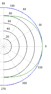
Figure 1 shows how loud a signal will be if you measure it at different directions relative to the face of a piston that is 10″ (25.4 cm) in diameter. Two frequencies are shown – 100 Hz (the blue curve) and 1.5 kHz (the green curve). Both curves have been normalised to be the same level (100 dB SPL – although the actual value really doesn’t matter) on axis (at 0°). As you can see in the plot, as you move off to the side (either to 90° or 270°) the blue curve stays at 100 dB SPL. So, no matter what your angle relative to on-axis to the woofer, 100 Hz will be the same level (assuming that you maintain your distance). However, look at the green curve in comparison. As you move off to the side, the 1.5 kHz tone drops by more than 20 dB. Remember that this also means that (if the loudspeaker is pointing at you and the sidewall is to the side of the loudspeaker) then 100 Hz and 1.5 kHz will both get to you at the same level. However, the reflection off the wall will have 20 dB more level at 100 Hz than at 1.5 kHz. This also means, generally, that there is more energy in the room at 100 Hz than there is at 1.5 kHz because, if you consider the entire radiation of the loudspeaker averaged over all directions at the same time the lower frequency is louder in more places.
This, in turn, means that, if all you have is a 10″ woofer and you play music, you’ll notice that the high frequency content sounds closer to you in the room than the low frequency content.
If the loudspeaker driver is smaller, the effect is the same, the only difference is that the effect happens at a higher frequency. For example, Figure 2, below shows the off-axis response for two frequencies emitted by a 1″ (2.54 cm) diameter piston (i.e. a tweeter).
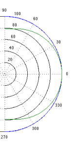
Notice that the effect is identical, however, now, 1.5 kHz is the “low frequency region for the small piston, so it radiates in all directions equally (seen as the blue curve). The high frequency (now 15 kHz) becomes lower and lower in level as you move off to the side of the driver, going as low as -20 dB at 90°.
So, again, if you’re listening to music through that tweeter, you’ll notice that the frequency content at 1.5 kHz sounds further away from the listening position than the content at 15 kHz. Again, the higher the frequency, the closer the image.
Same information, shown differently
If you trust me, figures 1 and 2, above, show you that the sound radiating off the front of a loudspeaker driver gets narrower with increasing frequency. If you don’t trust me (and you shouldn’t – I’m very untrustworthy…) then you’ll be saying “but you only showed me the behaviour at two frequencies… what about the others?” Well, let’s plot the same basic info differently, so that we can see more data.
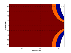
Figure 3, below, shows the same 10″ woofer, although now showing all frequencies from 20 Hz to 20 kHz, and all angles from -90° to +90°. However, now, instead of showing all levels (in dB) we’re only showing 3 values, at -1 dB, -3 dB, and -10 dB. ( These plots are a little tougher to read until you get used to them. However, if you’re used to looking at topographical maps, these are the same.)
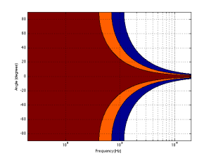
Now you can see that, as you get higher in frequency, the angles where you are within 1 dB of the on-axis response gets narrower, starting at about 400 Hz. This means that a 10″ diameter piston (which we are pretending to be a woofer) is “omnidirectional” up to 400 Hz, and then gets increasingly more directional as you go up.
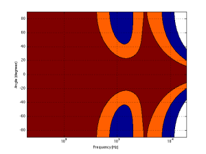
Figure 4 shows the same information for a 1″ diameter piston. Now you can see that the driver is omnidirectional up to about 4 kHz. (This is not a coincidence – the frequency is 10 times that of the woofer because the diameter is one tenth.)
Normally, however, you do not make a loudspeaker out of either a woofer or a tweeter – you put them together to cover the entire frequency range. So, let’s look at a plot of that behaviour. I’ve put together our two pistons using a 4th-order Linkwitz-Riley crossover at 1.5 kHz. I have also not included any weirdness caused by the separation of the drivers in space. This is theoretical world where the tweeter and the woofer are in the same place – an impossible coaxial loudspeaker.
In Figure 5 you can see the effects of the woofer’s directivity starting to beam below the crossover, and then the tweeter takes over and spreads the radiation wide again before it also narrows.
So what?
Why should you care about understanding the plot in Figure 5? Well, remember that the narrower the radiation of a loudspeaker, the closer the sound will appear to be to you. This means that, for the imaginary loudspeaker shown in Figure 5, if you’re playing a recording without additional reverberation, the low frequency stuff will sound far away (the same distance as the loudspeakers), So will a narrow band between 3 kHz and 4 kHz (where the tweeter pulls the radiation wider). However, the materials in the band around 700 Hz – 2 kHz and in the band above 7 kHz will sound much closer to you.
Another way to express this is to show a graph of the resulting level of the reverberant energy in the listening room relative to the direct sound, an example of which is shown in Figure 6. (This is a plot copied from “Acoustics and Psychoacoustics” by David Howard and Jamie Angus).
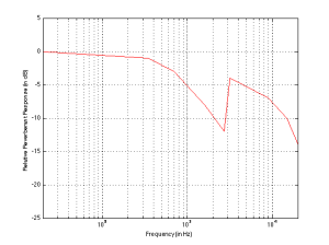
This shows a slightly different loudspeaker with a crossover just under 3 kHz. This is easy to see in the plot, since it’s where the tweeter starts putting more sound into the room, thus increasing the amount of reverberant energy.
What does all of this mean? Well, if we simplify a little, it means that things like voices will pull apart in terms of apparent distance. Consonant sounds like “s” and “t” will appear to be closer than vowels like “ooh”.
So, whaddya gonna do about it?
All of this is why one of the really important concerns of the acoustical engineers at Bang & Olufsen is the directivity of the loudspeakers. In a previous posting, I mentioned this a little – but then it was with regards to identifying issues related to diffraction. In that case, directivity is more of a method of identifying a basic problem. In this posting, however, I’m talking about a fundamental goal in the acoustical design of the loudspeaker.
For example, take a look at Figures 7 and 8 and compare them to Figure 9. It’s important to note here that these three plots show the directivities of three different loudspeakers with respect to their on-axis response. The way this is done is to measure the on-axis magnitude response, and call that the reference. Then you measure the magnitude response at a different angle, and then calculate the difference between that and the reference. In essence, you’re pretending that the on-axis response is flat. This is not to be interpreted that the three loudspeakers shown here have the same on-axis response. They don’t. Each is normalised to its own on-axis response. So we’re only considering how the loudspeaker compares to itself.
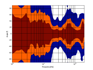
Figure 7, above, shows the directivity behaviour of a commercially-available 3-way loudspeaker (not from Bang & Olufsen). You can see that the woofer is increasingly beaming (the directivity gets narrow) up to the 3 – 5 kHz area. The midrange is beaming up above 10 kHz or so. So, a full band signal will sound distant in the low end, in the 6-7 kHz range and around 15 kHz. By comparison, signals at 2-4 kHz and 10-15 kHz will sound quite close.
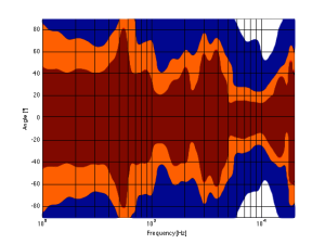
Figure 8, above, shows the directivity behaviour of a 3-way loudspeaker we made as a rough prototype. This is just a woofer, midrange and tweeter, each in its own MDF box – nothing fancy – except that the tweeter box is not as wide as the midrange box which is narrower than the woofer box. You can see that the woofer is beaming (the directivity gets narrow) just above 1 kHz – although it has a very weird wide directivity at around 650 Hz for some reason. The midrange is beaming up from 5kHz to 10 kHz, and then the tweeter gets wide. So, this loudspeaker will have the same problem as the commercial loudspeaker
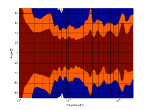
As you can see, the loudspeaker with the directivity shown in Figure 9 (the BeoLab 5) is much more constant as you change frequency (in other words, the lines are more parallel). It’s not perfect, but it’s a lot better than the other two – assuming that constant directivity is your goal. You can also see that the level of the signal that is within 1 dB of the on-axis response is quite wide compared with the loudspeakers in Figures 7 and 8. The loudspeaker in Figure 7 not only beams in the high frequencies, but also has some strange “lobes” where things are louder off-axis than they are on-axis (the red lines).
When you read B&O’s marketing materials about the reason why we use Acoustic Lenses in our loudspeakers, the main message is that it’s designed to spread the sound – especially the high frequencies – wider than a normal tweeter, so that everyone on the sofa can hear the high hat. This is true. However, if you ask one of the acoustical engineers who worked on the project, they’ll tell you that the real reason is to maintain constant directivity as well as possible in order to ensure that the direct-to-reverberant ratio in your listening room does not vary with frequency. However, that’s a difficult concept to explain in 1 or 2 sentences, so you won’t hear it mentioned often. However, if you read this paper (which was published just after the release of the BeoLab 5), for example, you’ll see that it was part of the original thinking behind the engineers on the project.
Addendum 1.
I’ve been thinking more about this since I wrote it. One thing that I realised that I should add was to draw a comparison to timbre. When you listen to music on your loudspeakers in your living room, in a best-case scenario, you hear the same timbral balance that the recording engineer and the mastering engineer heard when they worked on the recording. In theory, you should not hear more bass or less midrange or more treble than they heard. The directivity of the loudspeaker has a similar influence – but on the spatial performance of the loudspeakers instead of the timbral performance. You want a loudspeaker that doesn’t alter the relative apparent distances to sources in the mix – just like you don’t want the loudspeakers to alter the timbre by delivering too much high frequency content.
Addendum 2.
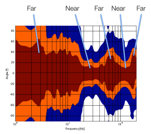
One more thing… I made the plot below to help simplify the connection between directivity and Grover. Hope this helps.
