#75 in a series of articles about the technology behind Bang & Olufsen loudspeakers
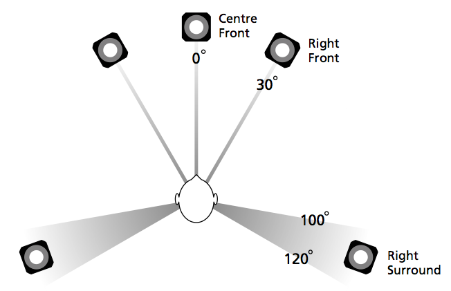
So, you’ve just installed a pair of loudspeakers, or a multichannel surround system. If you’re a normal person then you have not set up your system following the recommendations stated in the International Telecommunications Union’s document “Rec. ITU-R BS.775-1: MULTICHANNEL STEREOPHONIC SOUND SYSTEM WITH AND WITHOUT ACCOMPANYING PICTURE”. That document states that, in a best case, you should use a loudspeaker placement as is shown below in Figure 1.
In a typical configuration, the loudspeakers are NOT the same distance from the listening position – and this is a BIG problem if you’re worried about the accuracy of phantom image placement. Why is this? Well, let’s back up a little…
Localisation in the Real World
Let’s say that you and I were standing out in the middle of a snow-covered frozen pond on a quiet winter day. I stand some distance away from you and we have a conversation. When I’m doing the talking, the sound of my voice leaves my mouth and moves towards you.
If I’m directly in front of you, then the sound (in theory) arrives at both of your ears simultaneously (resulting in an Interaural Time Difference or ITD of 0 ms) and at exactly the same level (resulting in an Interaural Amplitude Difference or IAD of 0 dB). Your brain detects that the ITD is 0 ms and the IAD is 0 dB, and decides that I must be directly in front of you (or directly behind you, or above you – at least I must be somewhere on your sagittal plane…)
If I move slightly to your left, then two things happen, generally speaking. Firstly, the sound of my voice arrives at your left ear before your right ear because it’s closer to me. Secondly, the sound of my voice is generally louder in your left ear than in your right ear, not only because it’s closer, but (mostly) because your head shadows your right ear from the sound of my voice. So, you brain detects that my voice is earlier and louder in your left ear, so I must be somewhere on your left.
Of course, there are many other, smaller cues that tell you where the sound is coming from exactly – but we don’t need to get into those details today.
There are two important thing to note here. The first is that these two principal cues – the ITD and the IAD – are not equally important. If they got in a fight, the ITD would win. If a sound arrived at your left ear earlier, but was louder in your right ear, it would have to be a LOT louder in the right ear to convince you that you should ignore the ITD information…
The second thing is that the time differences we’re talking about are very very small. If I were directly to one side of you, looking directly at your left ear, say… then the sound would arrive at your right ear approximately only 700 µs – that’s 700 millionths of a second or 0.0007 seconds later than at your left ear.
So, the moral of this story so far is that we are very sensitive to differences in the time of arrival of a sound at our two ears.
Localisation in a reproduced world
Now go back to the same snow-covered frozen lake with a pair of loudspeakers instead of bringing me along, and set them up in a standard stereo configuration, where the listening position and the two loudspeakers form an equilateral triangle. This means that when you sit and listen to the signals coming out of the loudspeakers
- the two loudspeakers are the same distance from the listening position, and
- the left loudspeaker is 30º to the left of front-centre, and the right loudspeaker is 30º to the right of front-centre.
Have a seat and we’ll play some sound. To start, we’ll play the same sound in both loudspeakers at exactly the same time, and at exactly the same level. Initially, the sound from the left loudspeaker will reach your left ear, and the sound from the right loudspeaker reaches your right ear. A very short time later the sound from the left loudspeaker reaches your right ear and the sound from the right loudspeaker reaches your left ear (this effect is called Interaural Crosstalk – but that’s not important). After this, nothing happens, because you are sitting in the middle of a frozen lake covered in snow – so there are no reflections from anything.
Since the sounds in the two loudspeakers are identical, then the sounds in your ears are also identical to each other. And, just as is the case in real-life, if the sounds in your two ears are identical, you’ll localise the sound source as coming from somewhere on your sagittal plane. Due to some other details in the localisation cues that we’re not talking about here, chances are that you’ll hear the sound as originating from a position directly in front of you – between the two loudspeakers.
Because the apparent location of that sound is a position where there is no loudspeaker, it’e like a ghost – so it’s called a “phantom centre” image.
That’s the centre image, but how do we move the image slightly to one side or the other? It’s actually really easy – we just need to remember the effects of ITD and IAD, and do something similar.
So, if I play a sound out of both loudspeakers at exactly the same time, but I make one loudspeaker slightly louder than the other, then the phantom image will appear to come from a position that is closer to the louder loudspeaker. So, if the right channel is louder than the left channel, then the image appears to come from somewhere on the right. Eventually, if the right loudspeaker is louder enough (about 15 dB, give or take), then the image will appear to be in that loudspeaker.
Similarly, if I were to keep the levels of the two loudspeakers identical, but I were to play the sound out of the right loudspeaker a little earlier instead, then the phantom image will also move towards the earlier loudspeaker.
There have been many studies done to find out exactly what apparent phantom image position results from exactly what level or delay difference between the two loudspeakers (or a combination of the two). One of the first ones was done by Gert Simonsen in 1983, in which he found the following results.
[table]
Image Position, Amplitude difference, Time difference
0º, 0.0 dB, 0.0 ms
10º, 2.5 dB, 0.2 ms
20º, 5.5 dB, 0.44 ms
30º, 15.0 dB, 1.12 ms
[/table]
Note that this test was done with loudspeakers at ±30º – so the bottom line of the table means “in one of the loudspeakers”. Also, I have to be clear that the values in this table are NOT to be used concurrently. So, this shows the values that are needed to produce the desired phantom image location using EITHER amplitude differences OR time differences.
Again, the same two important points apply.
Firstly, the time differences are a more “powerful” cue than the amplitude differences. In other words, if the left loudspeaker is earlier, but the right loudspeaker is louder, you’ll hear the phantom image location towards the left, unless the right loudspeaker is a LOT louder.
Secondly, you are VERY sensitive to time differences. The left loudspeaker only needs to be 1.12 ms earlier than the right loudspeaker in order for the phantom image to move all the way into that loudspeaker. That’s equivalent to the left loudspeaker being about 38.5 cm closer than the right loudspeaker (because the speed of sound is about 344 m/s (depending on the temperature) and 0.00112 * 344 = 0.385 m).
Those last two paragraphs were the “punch line” – if the distances to the loudspeakers are NOT the same, then, unless you do something about it, you’ll wind up hearing your phantom images pulling towards the closer loudspeaker. And it doesn’t take much of an error in distance to produce a big effect.
Whaddya gonna do about it?
Almost every surround processor and Audio Video Receiver in the world gives you the option of entering the Speaker Distances in a menu somewhere. There are two possible reasons for this.
The first is not so important – it’s to align the sound at the listening position with the video. If you’re sitting 3 m from the loudspeakers and the TV, then the sound arrives 8.7 ms after you see the picture (the same is true if you are listening to a person speaking 3 m away from you). To eliminate this delay, the loudspeakers could produce the sound 8.7 ms too early, and the sound would reach you at the same time as you see the video. As I said, however, this is not a problem to lose much sleep over, unless you sit VERY far away from your television.
The second reason is very important, as we’ve already seen. If, as we established at the start of this posting, you’re a normal person, then your loudspeakers are not all the same distance from the listening position. This means that you should apply a delay to the closer loudspeaker(s) to get them to “wait” for the sound as it travels towards you from the further loudspeakers. That way, if you have the same sound in all channels at the same time, then the loudspeaker do NOT produce it at the same time, but it arrives at the listening position simultaneously, as it should.
Problem solved! Right?
Wrong.
Corrections that need correcting
Let’s make a configuration of a pair of loudspeakers and a listening position that is obviously wrong.
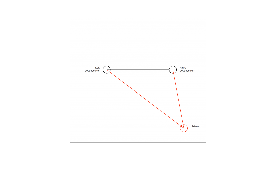
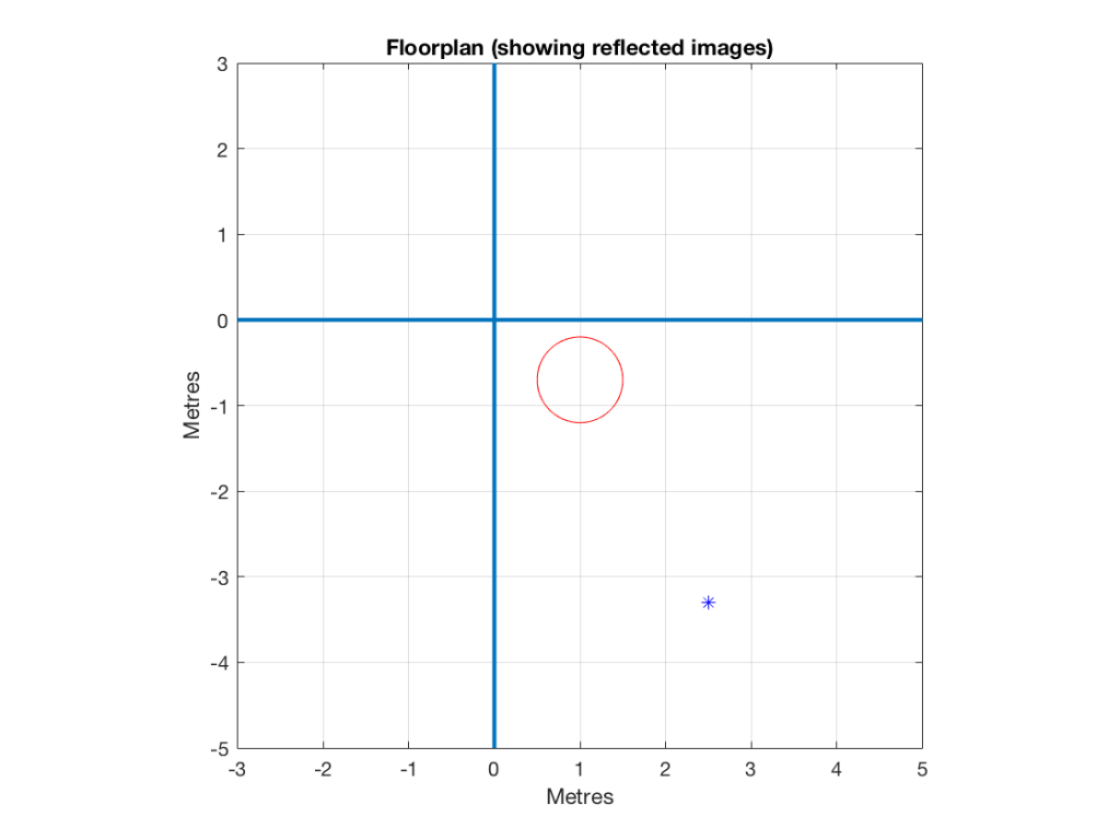
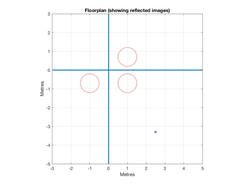
Figure 2 shows the example of a very bad loudspeaker configuration for stereo listening. (I’m keeping things restricted to two channels to keep things simple – but multichannel is the same…) The right loudspeaker is much closer than the left loudspeaker, so all phantom images will appear to “bunch together” into the right loudspeaker.
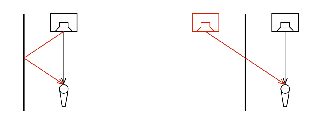
So, to do the correction, you measure the distances to the two loudspeakers from the listening position and enter those two values into the surround processor. It then subtracts the smaller distance from the larger distance, converts that to a delay time, and delays the closer loudspeaker by that amount to compensate for the difference.

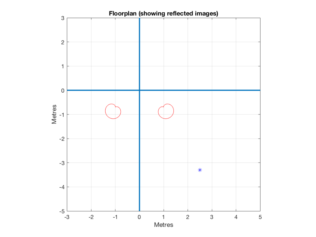
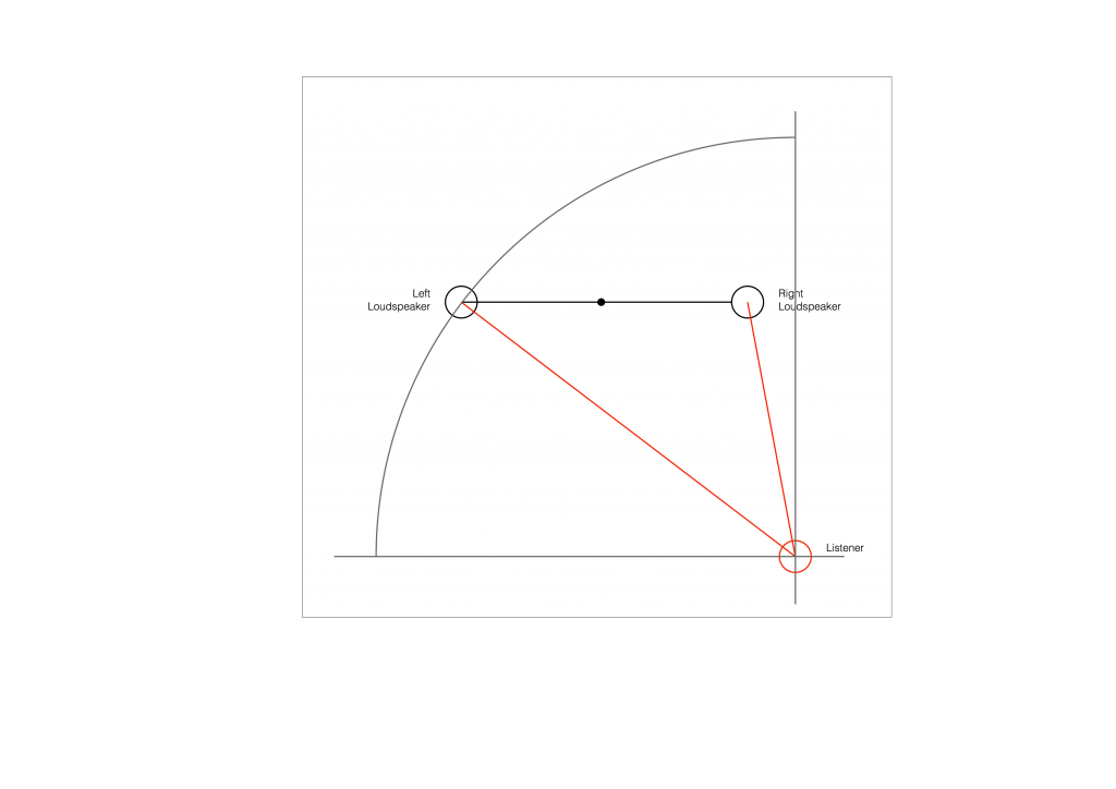
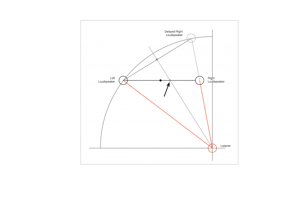
So, after the delay is applied to the closer loudspeaker, in theory, you have a stereo pair of loudspeakers that are equidistant from the listening position. This means that, instead of hearing (for example) the phantom centre images in the closer loudspeaker, you’ll hear it as being positioned at the centre point between the distant loudspeaker (the left one, in this example) and the “virtual” one (the right one in this example). This is shown below.

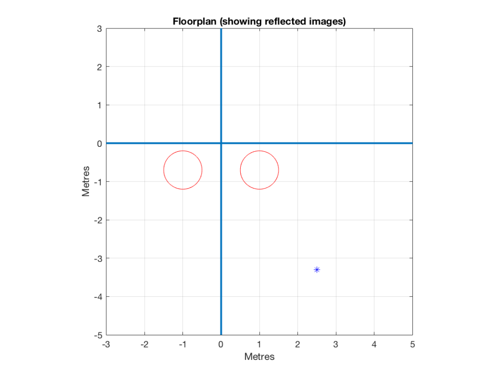
As you can see in Figure 6, the resulting phantom image is at the centre point between the two resulting loudspeakers. But, if you look not-too-carefully-at-all, then you can see that the angle from the listening position to that centre point is not the same angle as the centre point between the two REAL loudspeakers (the black dot).
So, this means that, if you use distances ONLY to time-align two (or more) loudspeakers, then your correction till not be perfect. And, the more incorrect your actual loudspeaker configuration, the more incorrect the correction will be.
How do I fix it?
Notice that, after “correction”, the phantom image is still pulling towards the closer loudspeaker.
As we saw above, in order to push a phantom centre image towards a loudspeaker, you have to make the sound in that loudspeaker earlier.
So, what we need to do, after the distance-based time alignment is done, is to force the more distant loudspeaker to be a little earlier than the closer one. That will pull the phantom image towards it.
In order to use a distance compensation to make a loudspeaker produce the sound earlier, we have to tell the processor that it’s further away than it actually is. This makes the processor “think” that it needs to send the sound out early to compensate for the extra propagation delay caused by the distance.
So, to make the further loudspeaker a little early relative to the other loudspeaker, we either have to tell the processor that it’s further away from the listening position than it really is, or we reduce the reported distance to the closer loudspeaker to delay it a little more.
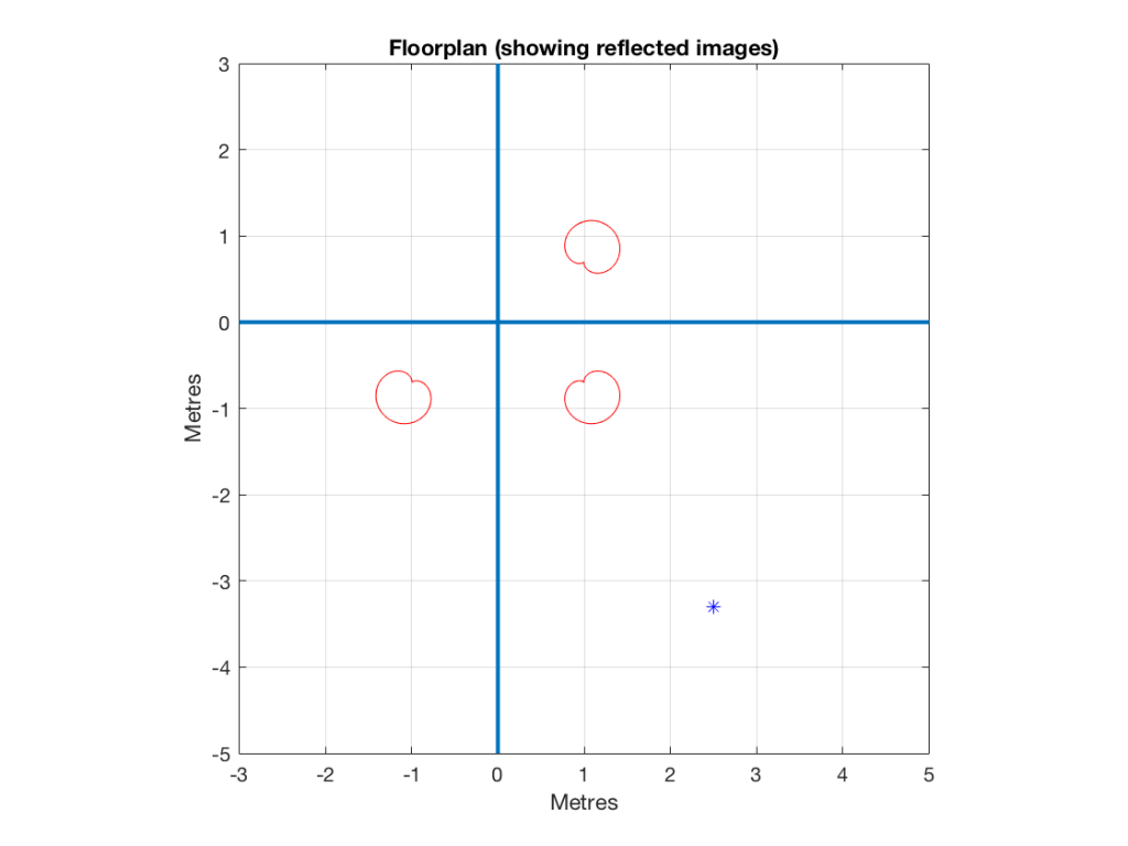
This means that, in the example shown in Figure 7, above, we should add a little to the distance to the left loudspeaker before entering the value in the menus, or subtract a little from the distance to the right loudspeaker instead.
How much is enough?
You might, at this point, be asking yourself “Why can’t this be done automatically? It’s just a little trigonometry, after all…”
If things were as simple as I’ve described here, then you’d be right – the math that is converting distance compensation to audio delays could include this offset, and everything would be fine.
The problem is that I’ve over-simplified a little on the way through. For example, not everyone hears exactly a 10º shift in phantom image with a 2.5 dB inter-channel amplitude difference. Those numbers are the average of a listening test with a number of subjects. Also, when other researchers have done the same test, they get slightly different results. (see this page for information).
Also, the directivity of the loudspeaker will have an influence (that is likely going to be frequency-dependent). So, if you’ve “toed in” your loudspeakers, then (in the example above) the further one will be “aimed” at you better than the closer one, which will have an influence on the perceived location of the phantom centre.
So, the only way to really do the final “tweaking” or “fine tuning” of the distance-compensation delays is to do it by listening.
Normally, I start by entering the distances correctly. Then, while sitting in the listening position, I use a monophonic track (Suzanne Vega singing “Tom’s Diner” works well) and I increase the distance in the surround processor’s menu of the loudspeaker that I want to pull the image towards. In other words, if the phantom centre appears to be located too far to the left, I “lie” to the surround processor and tell it that the right loudspeaker is further by 10 cm. I keep adding distance until the image is moved to the correct location.