Author: geoff
The Landfillharmonic
Just throw it out – it’ll be fine…
Les Mousserables
The Feel-good and Not-so-good movie of the year!
First Impressions
I’m sitting and listening to Mary Chapin Carpenter’s new album “Songs From the Movie” for the first time on Spotify on a pair of headphones.
I listen to a lot of recordings – usually to find problems in loudspeakers, so it’s not very often that an album makes the hair on the back of my neck stand up.
This one does.
I haven’t yet been able to find out who the recording engineer(s) was(were) for this album, but to whomever it was – Thanks!
BeoPlay Journal article
B&O Tech: Subwoofer Tweaking for Beginners
#8 in a series of articles about the technology behind Bang & Olufsen loudspeakers
In a previous post, I talked about why a subwoofer might be a smart addition to a sound system – and why a subwoofer brings something different to a Bang & Olufsen loudspeaker configuration than it does for other companies’ loudspeakers.
Usually, in a loudspeaker system that includes a subwoofer, the signal that is sent to that subwoofer is either
- coming in directly from the medium (say, the Blu-ray disc) from the LFE (Low Frequency Effects) channel OR
- created by something called a “bass management system” which is basically a mixer (something that adds audio signals) and some frequency division OR
- all of the above
Let’s assume, for the purposes of this article, that we’re talking about #3. So, let’s start by talking about how a system like that would work. The simple version is that you take an audio input, send it to two different filters, one called a “high pass filter” which lets the high frequencies pass through it and it makes the lower frequencies quieter. The second filter is called a “low pass filter” – you can figure that one out. The output of the high pass filter is sent to your “main” loudspeaker, and the output of the low pass filter is sent to the subwoofer.

That’s what happens if you have a good ol’ fashioned monophonic system with only one audio channel, one main loudspeaker and one subwoofer. Most people nowadays, however, have more than one main loudspeaker and lots of channels coming out of their players. So, in cases like that, we have to take the low end (the bass) out of each of the main channels using low pass filters, add the results all together, add the LFE channel to that, and send the total to the subwoofer. A simple version (with some important details left out, since we’re only talking about basic concepts here…) is shown in the diagram below.

Basics of Signal Addition
Let’s take an audio signal and add it to another audio signal – and, just to keep things simple, we’ll make them both sine waves. This is done by looking at the amplitude of the two signals at a given moment in time, adding those two values, and you get a result. For example:
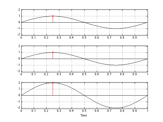
If you take a look at the example above, there are a couple of things that you can see. The first is that, if you add two sine waves, you get a sine wave. Also, if you add two sine waves of the same frequency, you get a sine wave of the same frequency. Next, if the two sine waves have the same amplitude and are “in phase”- basically meaning that they have the same value at the same time (sort of, but not really like a delay difference of 0) – the result is a sine wave that is in phase with the other two with double the amplitude of the two inputs.
Now, let’s move one of the two signals in time. We’ll make it late by half the length of the sine wave (in time) and see what happens.
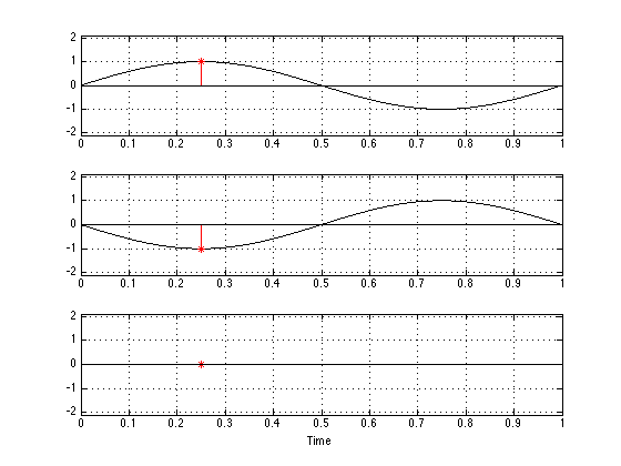
Now you can see that, since the bottom plot is the negative of the top plot at any given moment in time (because we’ve delayed it by half a “wave”), when you add them together, you get no output.
Let’s look at one last example, where the two input signals have some phase difference that is not quite so simple. This is shown in the figure below.
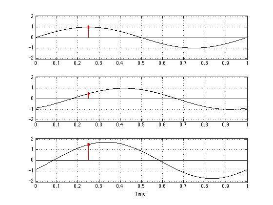
Again, you can see that, when you add two sine waves of the same frequency, you get another sine wave of the same frequency. You can also see that the phase (remember – phase is something like delay) of the result is not the same as the phase of either of the two inputs. Finally, you can see that the amplitude (the maximum value) of the result is neither 0 nor 2 – it’s something in between.
So, the moral of this story is that, if you have two sine waves then the result (what you hear) is (at least partly) dependent on how the two signals add – and that result might mean that you get something twice as loud as either input – or it could mean that you get nothing – or you get something in between.
The real world
The three plots shown above illustrate some simple examples of what happens when you have two sound sources that are added together to produce a result. For the purposes of this article, the two sources are two loudspeakers – the “main” loudspeaker and the subwoofer, and the result is the sum of those two signals at your listening position. Let’s go back to thinking about what frequency ranges are produced by these two loudspeakers. The plot below shows the magnitude responses of the filters in a BeoVision 11’s internal bass management system at its default crossover frequency of 120 Hz. The red curve shows the response of the low pass filter whose output is sent to the subwoofer output. The black curve shows the response of the high pass filter whose output is sent to a main loudspeaker.
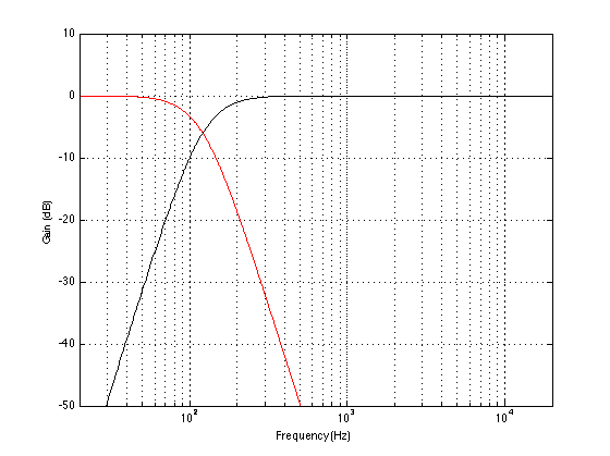
Take a look at the response of the signal that is processed by the low pass filter. You’ll notice that, although the “crossover frequency” is set to 120 Hz, there is still signal coming out of the filter (and therefore out of the subwoofer) above that frequency – it’s just getting quieter as you go further up and away from the crossover.
You might also notice that, at the crossover frequency, the level of the signal coming out of the low pass filter is identical to the level of the signal coming out of the high pass signal. That’s (more or less) what makes it the crossover frequency. As you move down from that frequency, you gradually get more out of the low pass (the sub) than the high pass (the main). As you move up in frequency, the opposite happens. However, there is a region around the crossover where both loudspeakers are contributing roughly equally (within reason) to the signal that you get at the listening position. So, the “truth” is a little more like the plot below:
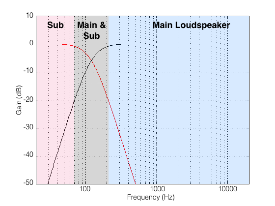
I’ve chosen -20 dB as the point where I can start ignoring a signal, but that’s a pretty arbitrary decision on my part. I could have set my threshold higher or lower and still argued that I was right. So, if you disagree with my choice of -20 dB as the threshold of “I don’t care any more” then I agree with you. :-)
By now, you should start to worry a little. You should be asking something like “hmmmm… you’re telling me that there is a big band of frequencies (say, roughly between 1 and 2 octaves) right around where human voice fundamental frequencies sit (well, at least my voice sits there – but I sing bass…) where a bass management system will send the signal out of two loudspeakers!? AND, to add insult to injury, you told me (in the previous section) that if the phases and amplitudes of those signals from those loudspeakers aren’t perfectly aligned, the result at the listening position won’t be the same as the input of the whole system?” If you ARE asking something like that, then you’re in good shape. As has been said by many other people in the past: the first step in fixing a problem is admitting you have one.
So, let’s ask a different question: what parts of the audio signal chain could affect either the amplitude or the phase of the signals coming out of the loudspeakers? Brace yourself… This list includes, but is not exclusive to:
- The characteristics of the filters in the bass management system
- The characteristics of the filtering in the loudspeakers
- The physical principal of the loudspeaker (i.e. sealed cabinets will be different from ported loudspeakers which are different from passive radiators)
- Diffraction (although this might be a small issue)
- Latencies (total delay) of the loudspeakers (for example, digital loudspeakers have a bigger delay than analogue ones typically)
- Distances of the loudspeakers to the listening position
- The characteristics of the room itself
- And more!
All of these issues (including the ones that fall under the “And more” category) have some effect on the phase (and amplitude) of the signal that you hear at the listening position. And, since some of these (like the distances and the room characteristics) are impossible for us (as a manufacturer) to predict, we have to give you, the end user, some way of adjusting your signals so that you can compensate for misbehaviour in your final system.
Now, although this is a “technical” article, I think that it would be too technical to start looking at the specifics of the phase responses of sealed cabinet vs ported loudspeakers, for example, since the details will be messed up by the listening room anyway. So, instead of getting into too many details, let’s just say that “you can’t expect your system to work perfectly without tweaking it” (see the reasons above) and just talk about some strategies for setting up your system so that it behaves as well as it can (without going out and hiring an acoustical consultant).
BeoLab 19 Controls
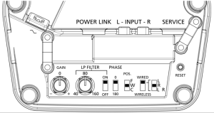
The BeoLab 19 has a number of controls that have not been available on previous B&O subwoofers. As a result they may cause a little confusion and playing with them without knowing what to expect or listen for could result in your system not performing as well as it could. On the other hand, it could be that these controls could help you improve your system if you’re finding that it’s not really behaving. Let’s take each control, one by one, and explain what it does, and talk about strategy afterwards.
Gain
The gain knob (on the left in the diagram above) is basically just a volume knob that controls how loud the subwoofer is overall. Let’s say, for example, that you have a perfectly configured system, then the outputs of the subwoofer and the main loudspeaker mate perfectly and result in a perfectly flat response below, through and above the crossover region. (this never happens in real life – but we can pretend). The diagram below shows an example of this, where the top plot shows the outputs of the subwoofer and main loudspeaker and the bottom plot shows the total result at the listening position.
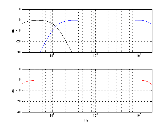
If you do nothing but change the gain of the subwoofer, (using the Gain knob on the BeoLab 19, for example) then the result would be something like the plot below.
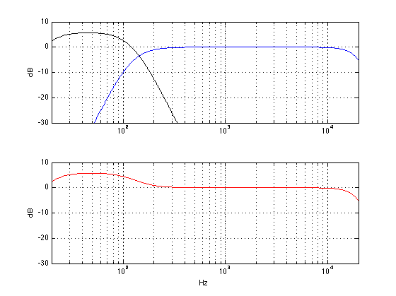
You can see in the plot above that all you do is to boost a region of low frequencies without doing anything strange through the crossover region. So, if you like bass, this might be a nice tweak for you. However, in theory, your goal is to get a response like the one in the first plot, where the outputs of the subwoofer and main loudspeakers have the same level (at the listening position).
LP Filter
One possible configuration of the BeoLab 19 is to connect it in parallel with your main loudspeakers and to not use and external bass management system.
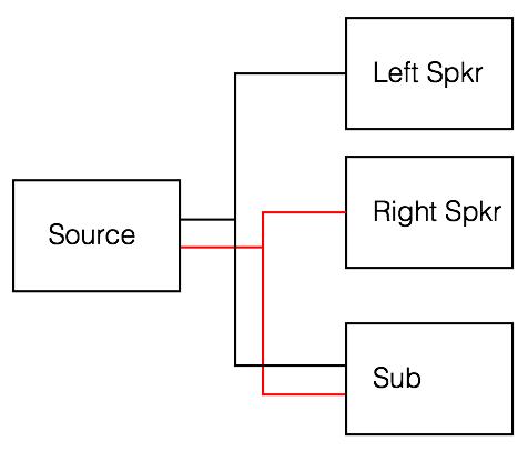
If you do this, then you are relying on the fact that the main loudspeakers have a high pass filter built-in, and you will align the low pass filter inside the BeoLab 19 to have approximately the same frequency so that the total result is a smooth-ish crossover region. In order for the low pass filter to work, you will have to turn it ON using the switch. (Note that, if you’re using an external bass management system as in the BeoVision 11, for example, then you should turn the low pass filter OFF, thus removing it from the signal path of the subwoofer.)
In theory, the goal here is to match the cutoff frequencies so the two loudspeakers behave nicely together across the crossover region. For example, if the natural low frequency cutoff is about 50 Hz, and you set the LPF in the subwoofer to 50 Hz, then you get the result below
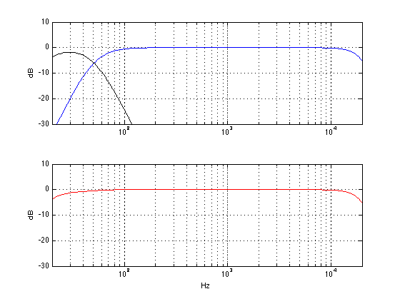
What would happen if you set the LPF incorrectly – let’s say that you make it higher than the correct value, since you would think that, by overlapping the sub with the main speaker, you’ll get more output and impress the neighbours. Well, the result would be the plot below.
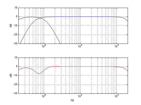
As you can see, although the sub is now delivering more signal (because it’s going all the way up to 120 Hz instead of 50 Hz in the previous plot), you actually get a reduction in the total output of the system. This may be initially counterintuitive, but it’s true in our example, since (as you may remember from something I said earlier in this article) the phase of the subwoofer is, in part, determined by the characteristics of the filtering in the loudspeaker. By changing the low pass filter frequency, we change the phase of the subwoofer in the crossover region and result in a cancellation with the main loudspeaker instead of a summing. In essence, both the sub and the main loudspeaker are now working very hard to cancel each other (especially around 80 Hz or so) and you hear very little at the listening position.
On the other hand, I have assumed here that the main loudspeaker’s high pass filter is a very specific type. A different main loudspeaker with a low frequency cutoff of 50 Hz would have had a completely different behaviour as you can see below.
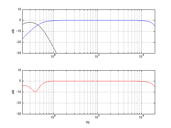
So, the moral of the story here is that setting the low pass filter frequency will have some effect on your total response. However, you should not jump to the conclusion that you can predict what the frequency should be – you will have to fiddle with the knob whilst listening to or measuring the total output of the system. You should also not jump to the conclusion that increasing the frequency range that is covered by the subwoofer in a parallel configuration will result in more output from your system. Overlap is not necessarily a good thing – sometimes, more is less…
Phase
Go back up and take a look at the two sine wave in the plots in Figure 4. One way to describe these two waves is to say that the middle one is half a wave later than the upper one – in other words, they are 180º out of phase. Another way to describe them is to say that the middle one is the inverse of the upper one – they have the same instantaneous value at any time, except that they are the negative of each other (in other words, signal 2 = signal 1 * -1).
So, intuitively, you can see that shifting the phase of a signal by 180º is the same as flipping it upside down. This could mean that, for example, all other things being ignored, that when a kick drum tells your subwoofer to push outwards, shifting the phase by 180º will result in your subwoofer sucking inwards instead. However, this is only true if all other things are being ignored. As soon as your subwoofer has a high pass filter (i.e. a low frequency limit) and a low pass filter (a high frequency limit) and it’s a loudspeaker driver in a cabinet in a room, all bets are off. All of those aspects (and more!) will have some effect on the phase of the system, so you can’t predict whether the kick drum will cause the woofer to put out or suck inwards.
So, instead of worrying about the “absolute phase” of the subwoofer, it’s more interesting to worry, once again, how it matches up with the main loudspeaker. Let’s take exactly the same responses from the plots shown in Figure 14 above (which didn’t add together so well for some reason) and shift the phase of the sub by 180º using the Phase switch. The result is shown below in Figure 15.
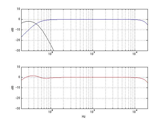
As you can see, the big dip in the total response of the system (seen in Figure 14) has been corrected, and we now have more output (actually, a little too much) below that. So, the result is that the total system response is much better than it was without flipping the phase switch.
Of course, if we flipped the phase switch in a system that was behaving nicely, then bad things might happen. Let’s flip the phase on the system shown in Figure 9, for example. That total result would look like the one in Figure 16, below.
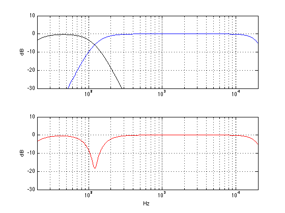
As you can see, you get the same amount of low bass in Figures 9 and 16. However, there is a nasty dip at the crossover frequency of 120 Hz when the two loudspeakers are cancelling each other.
So, the moral of the story here is that, if you have a problem in the crossover region between the main loudspeaker and the subwoofer, flipping the phase of one of the two might help the situation – although it might make things worse…
Pos (aka Position)
Almost every loudspeaker in the Bang & Olufsen portfolio has a switch that lets you change the characteristics of the loudspeaker to compensate for the differences in its response as a result of its placement in a room. Generally speaking, the closer you put a loudspeaker to a wall, the more bass you’ll get out of it. If you put it closer to two walls (i.e. in a corner) you’ll get even more bass. However, that is a very general characterisation – the reality is that you’ll get a little more at some frequencies and a little less in other frequencies – and that behaviour is dependent on the diameters of the loudspeaker drivers, the crossover frequencies, and the physical shape of the loudspeaker.
So, without getting into the details of exactly what is being changed in a BeoLab 19 (or BeoLab 2 or BeoLab 11 – or any other loudspeaker for that matter), let’s say that you should put the position switch in whatever setting best corresponds to the location of the loudspeaker in your room. However, if you want, you could cheat a little and fiddle with the switch to see if you like another setting more.
For example, if your loudspeaker is in the corner, and you put it in “free” mode, you’ll get LOTS of bass – too much bass. But if you like bass, this is one way to get it. Of course, there are other implications to this decision, but if you like bass enough, that might be reason enough to change to the “incorrect” the switch setting.
Wired / Wireless
The BeoLab 19 has the ability to receive its input via the analogue or digital input OR via the wireless receiver module that is built into it. This switch merely tells the loudspeaker whether it should “listen” to the wired input (either analogue or digital) or the wireless one. (Note that the BeoLab 2 and the BeoLab 11 do not have wireless receivers.)
L / R/ L+R
Most subwoofers (including the BeoLab 2 and the BeoLab 11) are built with the assumption that you will use them either:
- as a stand-alone subwoofer in a multichannel (i.e. 5.1 or 7.1) system where it gets the “.1” output from the source (that may, or may not have bass management) and so you just send one audio channel into it OR
- in a 2.1 setup where you want the left and right channels coming into the subwoofer where they are added together produce a mono bass signal internally
Consequently, most subwoofers either have 1 input (assuming that they are to be connected to the “subwoofer out” on something like an AVR) or a 2-channel stereo input (assuming that they should “see” left and right) that is summed to mono. BeoLab 2 and 11 are built based on the second assumption.
BeoLab 19 allows you to use the subwoofer in either of these configurations. So, in either “L” or “R” mode, it is only “listening to” the Left or Right audio channel on the Power Link input. In “L+R” mode, the input of the subwoofer is taking both audio input channels and summing them to make a mono input to the subwoofer. Note that, if you send exactly the same signal on the Left and Right audio channels on the Power Link cable, and then you switch the BeoLab 19 from either L or R to L+R, you’ll find that you get a doubling in the output level. This is because a signal plus itself is twice as loud. Since this is what BeoLab 2 and 11 do all the time, if you simply replace a BeoLab 2 or 11 with a BeoLab 19, you should put the 19 in “L+R” mode – otherwise you’ll lose some bass in your system.
However, if you want to use a single Power Link cable to run to the Subwoofer and to another loudspeaker (say, a centre channel, for example), then you should put the BeoLab 19 in either L or R mode (and the other loudspeaker in the opposite mode) so that you can access both loudspeakers independently. This is also the case if you want to run two BeoLab 19’s on the same Power Link cable and use the 2-channel LFE output option in a BeoVision 11. In this case, you se one BeoLab 19 to “L”, the other to “R” and set the Speaker Roles in the BeoVision 11 to “Sub Left” and “Sub Right” (or “Sub Front” and “Sub Back”) appropriately.
Note that, if you are in Wireless mode, the “L/R/L+R” switch does nothing.
How to do it (Finally!)
Method for an Externally Bass Managed Configuration
If your main loudspeakers and your subwoofer are connected to a system that has a bass management system, then you should use it. There are a number of reasons for this:
- the main loudspeakers may behave better (for example, with respect to distortion or port noise) if they are not being pushed by a lot of bass
- a bass management system will work for a multichannel loudspeaker system
- a bass management system (for example, in a BeoVision 11) will be capable of making some “intelligent” decisions with respect to your entire system
- a good bass management system (for example, in a BeoVision 11) will allow you to make fine adjustments to accommodate your configuration and room
So, your procedure here (assuming that you have a BeoVision 11 and a BeoLab 19 and some main loudspeakers) is as follows:
- Turn off the LP Filter on the BeoLab 19, set the Phase to 0, set the Gain to 0, and set the other switches to whatever is best for your particular configuration.
- Put the correct loudspeaker models into the Speaker Connections menu on the BV11.
This will compensate for differences in the latencies and sensitivities of the loudspeakers, in addition to making some intelligent decisions about where to route the bass. - Set your Speaker Distances correctly
This will ensure that you do not have phase differences in the loudspeakers at the listening position as a result of problems caused by the speed of sound and mis-matched distances. - Set your Speaker Levels correctly
On a BeoVision 11, this is done by making sure that, at the same volume level, all loudspeakers produce the same level in “dB SPL, C-weighted, Slow” on an SPL meter like this one, or this one, or this one, for example. - Turn on a piece of music that has a constant bass level
The opening of Freddy Mercury’s “Living on my Own” or Santanta’s “You Are My Kind” are a possible tunes. Claire Martin singing “Black Coffee” is also a good candidate. If you want to look like a professional, then I suppose that you could use pink noise or this track instead of music. - Sit in the listening position and listen to the total behaviour of the system. Pay particular attention to “unevenness in the bass”. In other words, listen to the bass and pay attention to whether some notes are quieter or louder than others.
- In theory, if you performed Step 4 correctly, then you shouldn’t have to play with the Speaker Level in the TV or the Gain on the subwoofer.
- If there is a general area somewhere in the middle of the bass where lots of notes are too quiet, try flipping the phase on the subwoofer.
- If some individual frequencies (or notes) are quiet then playing with the allpass filter on the TV might help.
- If some individual frequencies (or notes) are louder than others, this is probably caused by the room, and you might be able to deal with it by moving the subwoofer. If, when you put the sub in the corner, you make this problem worse, it is almost certainly the room acoustics that you’re dealing with, so moving the sub is your best bet.
Method for a Parallel Connection Configuration
- Turn the LPF frequency as low as you can go
- Turn on a piece of music that has a constant bass level
- The opening of Freddy Mercury’s “Living on my Own” or Santanta’s “You Are My Kind” are a possible tunes. Claire Martin singing “Black Coffee” is also a good candidate. If you want to look like a professional, then I suppose that you could use pink noise or this track instead of music.
- Sit in the listening position and ask someone to turn the LPF as low as it will go.
You should notice that there is a “hole” in the level of the bass between the subwoofer and the main loudspeaker. Turn up the LPF frequency and pay attention whether the “hole” fills up or gets worse. If it gets worse, flip the phase switch and start Step 4 again. - If the hole did not get worse, then keep turning up the LPF frequency until it sounds like there the hole is filled up.
- One you’re done playing with the LPF frequency, try moving the Gain to adjust the bass to the level that you like.
Addendum
There are some more examples of what happens when you play with the various knobs on a subwoofer here.
Loudspeakers are not just for making noises…
B&O Tech: What is Sound Design?
#7 in a series of articles about the technology behind Bang & Olufsen loudspeakers
My official job title at Bang & Olufsen is “Tonmeister and Technology Specialist in Sound Design”. The second half of that title is a bit weird – what is a “sound designer” and why would B&O want to have one on staff?
To answer that question, let’s start by talking about how a loudspeaker behaves in a real room. In many respects, a loudspeaker is like a lamp. Turn on a lamp and look at where the light goes. Some of it goes directly on what you want to look at – like the book you’re trying to read, for example. More of the light goes in other directions – it radiates outwards and reflects off of the walls, floor, ceiling, and furniture. And, if your lamp is anything like the one in my living room, then the light that shines directly on your book is not the most important part. In fact, if there was no direct light shining on the book, you would probably still be able to read your book because of the light reflecting towards your book off of everything else in the room.
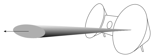
A loudspeaker is basically the same thing – you have some sound that radiates directly out of the loudspeaker towards the listening position (assuming that the loudspeaker is “aimed” at the listening position) like a laser beam (like the light shining directly on your book – this is called the loudspeaker’s “on-axis magnitude response” or the “frequency response“). In addition to this, you have the sound that radiates outwards in all directions simultaneously like a big ball expanding in all three dimensions (this is called the “power response” of the loudspeaker). There are a couple of things to think about here. The first is that the sound that is coming directly from the loudspeaker to the listening position isn’t necessarily in the direction that the people who built the loudspeaker would call “on-axis” – in fact, more than likely, it’s slightly off-axis. This is okay, since you can think of a loudspeaker’s principal axis of radiation more like the beam from a flashlight than a laser beam (so you have a “listening window” instead of a single spot). The second thing to remember is that, in most listening situations, you are hearing FAR more energy from the loudspeaker’s total power response than you do from the direct sound’s magnitude response. In fact, in a lot of situations, you don’t have any direct sound at all – just power response filling up the room and reflected back to you. (If you’d like to learn more about this concept, read this posting to start off.)
The (rather important) moral of this short story is that the power response is at least as important as the magnitude response – and usually much more important. The problem is that, if you read loudspeaker reviews in magazines, you get the impression that the on-axis magnitude response is the most important thing there is to know about a loudspeaker. This is simply not true – the on-axis response of a loudspeaker is one of the easier things to measure, so that’s what gets measured by most people. It’s very difficult to do a reliable power response measurement, so most people don’t do one. Keep this in mind as you keep reading.
So, what are the steps we take when we tune our loudspeakers during the development process?
Step #1: Measurements
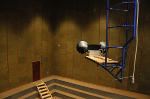
The prototype is put on the crane in the Cube and the linear part of its acoustic response is measured by the acoustical engineer assigned to the project. The output from these measurements consists of four final measurements:
- the on-axis frequency response
- the frequency response of the loudspeaker at a lot of different angles in all directions (not just around the loudspeaker’s “equator” but also above and below it)
- a kind of an average response in a “listening window”
- the power response (made by adding the results of all the measurements done in all directions)
Since we make DSP-based active loudspeakers (unlike passive loudspeakers) the angular direction that is chosen as the “on-axis” location is arbitrary. This is because the final response from each loudspeaker driver and the delays that are used to time-align them are determined by the filtering that we apply in the DSP. I’ll talk about this in a future posting. However, what this means is that “on-axis” is “wherever we decide it to be” – NOT “directly in front of the tweeter” or “directly in front of the loudspeaker”. So, we do a measurement of the frequency response (which is comprised of the magnitude response and the phase response) of the loudspeaker in the absence of any wall reflections at some distance, on a line that has been determined to be the “on-axis” direction.
The power response of a loudspeaker is kind-of-sort-of the sum of its magnitude responses in all directions. This is essentially a measure of the total acoustic energy that a loudspeaker sends into a room in all directions at the same time. So, instead of thinking of a loudspeaker as a laser beam (as in the on-axis response), this considers the loudspeaker as a naked light bulb, sending sound everywhere (which is actually a little closer to the truth).
The listening window is an area that has the on-axis line as its centre. It’s an oval-shaped area that is wider than it is high, that represents an area in front of the loudspeaker where we think that this listeners will typically be located.
In the old days (actually, for all of the active loudspeakers before BeoSound 8), the result of this process would have been two filters. The first would be a correction filter made by the acoustical engineer that made the loudspeaker’s on-axis frequency response flat in its magnitude response. The second would have made the power response smooth (i.e. without too many dips and bumps). Then the loudspeaker would have gone into the listening room, with those two filters as two different options as starting points for the listening-based sound tuning.
Nowadays, we do things a little differently, the measurements that are performed in the listening window (between 10 and 20 measurements in total) are compared and analysed for common aspects in their time responses. In other words, we’re checking to see whether the loudspeaker has natural resonances in it that causes it to “ring” in time (just like a bell rings when you hit it). Ringing is a natural behaviour of a loudspeaker, but that doesn’t mean it’s a good thing – it means that some frequency (the one that’s ringing) lasts longer than the others when you hit the loudspeaker with a signal (usually it’s ringing at lots of different frequencies). Depending on what frequencies are ringing, the result could be a “muddy”- or a “harsh”-sounding loudspeaker (to name just two of many descriptors meaning “bad”…) If we can see the same ringing in all (or at least most) of the measurements in the listening window, then the DSP engineer working on the project will make a filter for the signal processing that makes the ringing go away – in essence, we make the signal that we’re sending into the loudspeaker ring opposite to the natural ringing of the loudspeaker itself. You can think of it like kicking your legs in the wrong direction when you’re on a swing to make yourself slow down – you’re actively working in the opposite direction of the natural resonance of the system (where you-on-the-swing is “the system”).
In addition to making the resonances go away, we add filters to
- push the low frequency response to go as low as we want it to
- ensure that the loudspeaker drivers (for example, the woofer and the tweeter) meet each other correctly through the crossover and work together instead of against each other. In order to do this correctly, you can’t just build a crossover – you have to incorporate the natural frequency responses of the loudspeaker drivers as part of the total filter design.
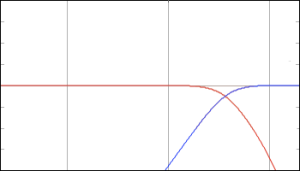
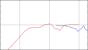
At the end of this process, we have a loudspeaker that has a final response that has been corrected so that it measures well inside the listening window. We also have a bunch of measurements that we’ll probably come back to later.
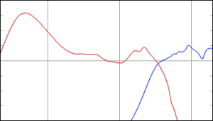
Step #2: Tuning
The prototype with its correction filters are brought into the listening room and we start playing music through it. The first thing to do is just sit and listen using recordings that we know really well (usually, for me, that means starting with “Bird on a Wire” by Jennifer Warnes from Famous Blue Raincoat – I’d guess that I have heard that song, on average, once a day, every day, since about 1990 or so). Pretty soon, some problem will be apparent. Depending on the problem that shows up, we’ll try to fix it by correcting the physical reason for the problem. (This is done by the acoustical engineer working with the mechanical engineers to sort out where the problem occurs and how to fix it.) For example, if a part of the loudspeaker cabinet is vibrating and “singing along” with the loudspeaker, we’ll stiffen the cabinet, either by increasing its thickness, or changing the material it’s made out of, or adding ribs or bulkheads or some combination of those things. Once that problem is fixed, we bring it back into the listening room, find another problem, fix it, listen, complain, fix, listen, complain, fix, rinse, repeat, etc. etc…
Eventually, once all of the problems that we can fix with physical corrections are done, we start the next phase of the tuning. This is where the “design” part of the sound design comes in…
We set up the loudspeaker with its correction filters and its physical improvements in the listening room and start listening to music again. Now, if something sticks out as sounding wrong in the recording, we use an equaliser to correct it. If a note is sticking out that shouldn’t be, then we put in a dip in the equalisation to reduce the problem. If there’s some frequency band that seems to be missing, then we’ll use an equaliser to boost it a little to get it back. Typically, that process takes about 3 to 5 days in the listening room, and at the end, we have something between 20 and 40 extra equalisers in the signal flow. When that’s done, we pack up and go to a different listening room and start the process from scratch again. A couple of days later, we have another 20 – 40 filters. Then we pack up and go to a different room and start again. That process is done in something like 4 or 5 rooms, depending on the loudspeaker that we’re working on. Usually, we try to use rooms that are different from reach other, but also that will be representative of the acoustic behaviours of the rooms that the products will be used in. For example, when we were tuning the BeoPlay A9, one of the “rooms” was outdoors in the acoustical engineer’s back yard. This was because some customers will put their A9 out on the back deck or by the pool – so we used that situation as one of our tuning rooms.
So, now we have 4 or 5 sets of tunings, each with about 30 equalisers in them (give or take…). These tunings are then analysed to see what is common amongst them. You see, if we were to just tune a loudspeaker in a single position in a single room, a big part of the tuning would be there to correct the acoustical behaviour of the room. For example, in our main listening room in Struer, we have a pretty nasty room mode that rings at about 55 Hz. Whenever I tune a loudspeaker in that room, I put in a notch filter at 55 Hz to reduce the audibility of the problem (especially since I start tuning using Bird on a Wire, and it’s in A Major, and 55 Hz is an A). However, if your living room is not the same size as Listening Room 1 in Struer, then your room modes will be at different frequencies, so you should have a notch filter at those frequencies instead of 55 Hz. So, in order to eliminate the individual corrections for the individual rooms that we used for tuning the loudspeaker, we just take the common aspects from each tuning. For example, if the first tuning has a dip at 55 Hz and a boost at 200 Hz, and the second tuning has a dip at 65 Hz and a boost at 200 Hz – we only keep the 200 Hz boost (since the notches at 55 Hz and 65 Hz are probably due to the rooms, not the loudspeaker itself).
Once the common aspects of all those tunings have been extracted, we use those to build an equalisation that is, essentially, the sound design. That equalisation is built into the loudspeaker, and we start getting more people to listen to it in more rooms (for example, we’ll send people home with prototypes that include the sound design tuning to get “real world” testing).
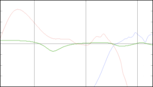
Why do you need Sound Design?
Of course, there are purists amongst you who will ask why it is that we need the sound design process in the first place. The logic goes that if you make a loudspeaker with a razor-flat on-axis frequency response, then you will get a perfect loudspeaker – end of story. Anything that is done afterwards to muck about with that response is just ruining the loudspeaker. Ignoring a lot of details, this would be true if you used your loudspeaker in a room that had no reflections – in other words, if all you hear is the on-axis sound, and all of that energy that goes in all other directions never reflects off of anything else and bounces back at you, then a flat on-axis response would probably be a good idea.
However, think back to where we started. We said that the power response of the loudspeaker is at least as, if not more, important than the on-axis magnitude response. This means that the sound that radiates away from the loudspeaker in directions other than yours is what you hear most of the time. The relationship between the on-axis magnitude response and the power response is determined by the physical shape of the loudspeaker and its components (as well as the frequencies of the crossovers). And, how that balance between the on-axis response and the power response is perceived at the listening position (wherever that might be…) is really unpredictable. So, rather than building a tuning that is based on a prediction, we experience it instead – by playing the loudspeaker in different rooms and different positions and assembling some sort of average behaviour in the real world.
One of the statements I’ve made on Bang & Olufsen marketing materials in the past (like this video, for example) is that, when you sit in your living room and listen to a pair of B&O loudspeakers, you should hear what the mastering engineer (or the mixing engineer, or the recording engineer) heard when he or she did the recording using professional studio monitor loudspeakers in a mastering or recording studio. (Note that this is very different from the philosophy that you should be able to sit in your living room, close your eyes, and be fooled into thinking that the musicians are standing in front of you. In my opinion this is a silly philosophy, akin to believing that you should go to a movie theatre and believe that you’re in the movie instead of watching it. A music recording should be better than real life – not the same as it. And, please – before you write a comment below telling me that I’m wrong, read this first – then this – and then come back and write a comment below telling me that I’m wrong.) However, since your living room is not a mastering studio, it doesn’t make sense for you to use studio monitors. In other words, the goal is that the combination of B&O loudspeakers and your living room should be the same as studio monitors and a recording studio.
So, the moral of the story is that the goal of sound design (at least at Bang & Olufsen…) is to ensure that our loudspeakers in a normal room (whatever that means for a given product) sounds like professional studio monitors in a recording studio. In other words, if we started making studio monitors instead of home loudspeakers, I’d be out of a job, since we wouldn’t need a sound design procedure to “undo” the effect the room has on our loudspeakers…
P.S
One thing that I did not talk about here (mostly just to keep things clear) was the off-axis responses of the loudspeaker, the collection of which comprises its directivity. That discussion will be left for a future posting.
P.P.S.
There is one aspect of this article that can explain one issue that some people have with B&O loudspeakers. If you take a look at some magazine reviews and some comments from people-who-post-opinions-about-loudspeakers-late-at-night-on-Internet-fora, they’ll say that our loudspeakers are obviously not worth anything, since they do not have a flat on-axis frequency response. Of course, if the only criterion you use to define what makes a loudspeaker “good” is a one-dimensional measurement at a single point in space, then you might be inclined to agree with that opinion.
However, if, like me, you live in three dimensional space in a house that has walls, floors and ceilings – and you have more than one chair and possibly even a friend or two – you might be inclined to think differently…
B&O Tech: What are subwoofers REALLY for?
#6 in a series of articles about the technology behind Bang & Olufsen loudspeakers
The Setup
Back in a previous posting, I said something that could be perceived as interesting… The short version of what I said there was that, if you’re making a DSP-based active loudspeaker (like all of the new loudspeakers in the B&O portfolio), you can essentially make it sound like whatever you want. You do this by adding filters in the digital signal processing (DSP). (Let’s assume for this article that we’re only talking about the on-axis magnitude response of the loudspeaker, and we’re working in an anechoic environment (aka a “free field” situation), since that will keep things simple.) This means that, if I can apply enough boosts and cuts, I can get any magnitude response I want out of the loudspeaker. In other words, I can have a 1″ tweeter that plays with a perfectly flat response from 20 Hz to 20 kHz.
However, there are some serious restrictions on this statement. As a minor example, if there is a problem with diffraction the only way to change that is to modify the shape of the loudspeaker cabinet (if you don’t know what diffraction is, don’t worry – it will not be mentioned again in this article).
However, there is one GIANT restriction on the statement that we’ll look at this week. This is a question of how loudly you want to play. So let’s look at that.
In order to make sound, a loudspeaker driver has to move in and out – this pushes and pulls the air molecules in front of it, creating small areas of higher pressure and lower pressure (relative to today’s natural barometric pressure) that radiate outwards, away from the driver. Those variations in pressure push and pull your eardrum in and out of your head which, in turn cause stuff to happen in your inner ear which, in turn causes stuff to happen in your brain – but that is all outside the scope of this discussion.
Back to the loudspeaker – it has to move in and out. The louder you want to play (more accurately, the higher the Sound Pressure Level (SPL), the more it has to move in and out. Also, the lower in frequency you want to play, he more it has to move in and out (to keep the same SPL).
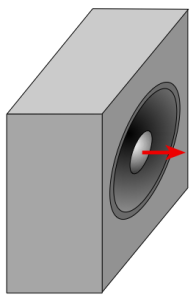
The real problem is the second of these, since the rule of thumb is that, every time you go down one octave (in other words, you divide the frequency by 2) you need to quadruple the excursion of the driver (the amount it moves in and out).
Let’s look at an example. The figure below illustrates the excursion required for different sizes of loudspeaker drivers in order to create a sound pressure level of 60 dB SPL (which is not very loud – but is a typical sort of listening level) at 1 m (which is a good approximation for how loud it will be all over your living room due to something called the room’s “critical distance” – we’ll talk about that in the future).
Notice that, for the 15″ woofer, it only has to move 0.08 mm out of the box (and 0.08 mm into the box) to produce a 20 Hz signal at 60 dB SPL. This is not very much movement. By comparison, the 4″ woofer has to move 1.2 mm which is much more than 0.08 mm, but still not much.
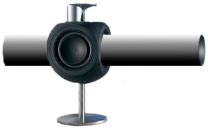
To bring this into the real world, this means that a woofer taken out of a BeoLab 3 (which is 4″ in diameter) would have to move 14 times farther than a woofer from a BeoLab 5 (15″ woofer) to produce the same output. This is because the 4″ woofer is smaller than the 15″, so to move the same number of air molecules, we have to move it more. (actually, what we’re really thinking about here is how many litres of air we’re moving, but that might be too much detail…)
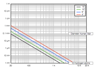
Let’s consider the practical implications of this graph. Since a BeoLab 3 woofer can move 1.2 mm in and out (and, of course, a BeoLab 5 woofer can move 0.08 mm). Both loudspeakers are able to produce a 20 Hz tone at 60 dB SPL. Therefore, if we choose to do so, we can make both loudspeakers have a magnitude response that was flat from 20 Hz to 20 kHz at this listening level (or quieter).
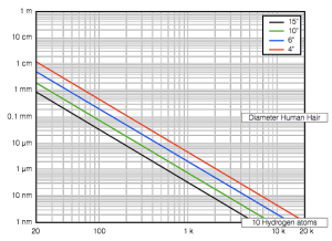
Let’s turn up the volume knob. We’ll go up to 80 dB SPL which is a bit loud, but certainly not enough to get the party going… Now we need to move the 15″ woofer 0.8 mm (still not very much…) and the 4″ woofer 11.6 mm to produce 20 Hz at 80 dB SPL. Of course, the BeoLab 5 woofer can easily move 0.8 mm, but 11.6 mm is too far to go for the BeoLab 3 woofer. So, if we didn’t have ABL to protect things from moving too far, we would not be able to tune the BeoLab 3 to be flat down to 20 Hz – we would have to “roll off” the low frequencies so that 20 Hz was not as loud as the frequencies above 20 Hz in order to prevent it from causing the woofer to move to far when you turn up the volume. (For example, we could tune it to be flat down to 40 Hz instead of all the way to 20 Hz.)
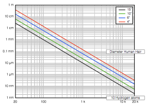
Let’s go further, just to make things really obvious. We’ll turn up the volume to 110 dB SPL (which is very loud). Now, to get a 20 Hz tone out at this level, the 15″ driver will have to move 2.6 cm and the BeoLab 3 woofer would have to move 36.6 cm (which is silly). So, here it is obvious that, if we want to build the BeoLab 3 to play 110 dB SPL, we will have to use ABL or limit its low frequency content (or use some balance of those two things – a little ABL and a little higher low-frequency limit).
Let’s look at this in another, more intuitive way. If we wanted a BeoLab 3 woofer to play as loudly as a BeoLab 5 woofer can play, at its peak excursion in and out of the cabinet, it would look like the figure below.
The Implications
So, what does this mean? Well, it means two things:
- for normal listening levels, we can use our DSP to make our loudspeakers have as much bass as we choose
- however, this means that we need ABL to reduce the bass at higher listening levels
But, what happens if you want to buy BeoLab 3’s (or another “small” loudspeaker in the B&O portfolio), but you don’t want to lose bass output at high listening levels? Well, you have two choices:
- buy bigger loudspeakers
- buy a “subwoofer”
“What’s a subwoofer?” I hear you cry. Well, let’s be honest to start. In theory, a subwoofer is a loudspeaker that should play frequencies that are below the limits of the woofer. (In a system with passive loudspeakers, this would actually be true.) However, in a DSP-based, fully-active loudspeaker system, a subwoofer has a slightly different role. In the case of a Bang & Olufsen system, a subwoofer behaves more like a woofer with more ability to play loudly than the main loudspeakers.
For example, if you have a pair of small loudspeakers (let’s say, the built-in loudspeakers in a BeoVision 11, for example) and you add an external subwoofer (say, a BeoLab 19), and you’re listening at normal listening levels, then (all other things being equal) turning the subwoofer on and off should not produce a noticeable change in the bass level. In fact, if you turn on the subwoofer and hear a difference, it means that the subwoofer is too loud.
However, if you turn up the volume, you will get to a point where the “small” loudspeakers cannot produce enough output at low frequencies, so the ABL starts turning down the bass to protect the loudspeakers from distorting. Now, since the subwoofer can play louder at low frequencies, you will notice the difference.
Of course, this assumes that you’re using something called “bass management” which is an algorithm that removes the bass from the signals sent to your small loudspeakers and re-directs it to the more capable subwoofer. So, in the example above, where I was suggesting that you were turning your subwoofer on and off, I should have been more specific, since turning your subwoofer on implies that you’ve removed bass from the small loudspeakers at the same time.
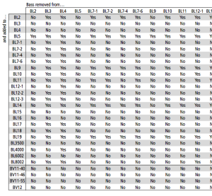
This has a secondary implication. This means that, if you have a two different types of main loudspeakers (i.e. BeoLab 5 in as your front Left / Right pair and BeoLab 12 and your surround Left / Right pair) then we can do the same “trick”. So, the bass management system should “know” that the 5’s have more capability to play low frequencies louder than the 12’s and automatically direct the bass from the surround channels to the BeoLab 5’s in the front (therefore making the BeoLab 5’s the front loudspeakers and the subwoofers). And, if we were REALLY smart, the “brain” at the centre of the system would know the bass capabilities of all loudspeakers that are attached to it and be able to make intelligent decisions about who should get the bass. This is exactly what is happening in the BeoVision 11, BeoPlay V1 and BeoSystem 4. When you enter your Speaker Types (the model numbers of the loudspeakers in your configuration), the software inside the television automatically decides whether the bass should be redirected from a given loudspeaker in the configuration to another loudspeaker, based on the maximum outputs of those loudspeakers at low frequencies. (This entire lookup table is shown in the Technical Sound Guide available here – a small section of the table is shown below.)
There is one small thing that I haven’t mentioned, but some sticklers-for-detail will want that I do so… The reason you can get away with doing this whole bass-redirection-trick is that, in a normal listening room, we humans are worse at localising where low frequencies are coming from than we are for higher frequencies. This inability on our part can therefore be exploited by moving the bass to a different loudspeaker. However, there are some people who say that this inability is over-estimated (in other words, some people say that we’re better at locating subwoofers than most people think we are) however, that debate can probably be addressed by discussing the size of the room and how low a frequency is “low” – and those are just excruciating minutiae (at least, within the limits of this article…)
