Mixing closed and ported cabinets: Part 2

Let’s look at a typical moving coil loudspeaker driver like the woofer shown in Figure 1.
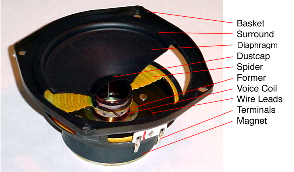
Figure 1.

If I were to draw a cross-section of this and display it upside-down, it would look like Figure 2.
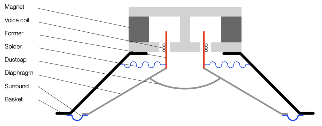
Figure 2.

Typically, if we send a positive voltage/current signal to a driver (say, the attack of a kick drum to a woofer) then it moves “forwards” or “outwards” (from the cabinet, for example). It then returns to the rest position. If we send it a negative signal, then it moves “backwards” or “inwards”. This movement is shown in Figure 3.

Figure 3.

Notice in Figure 3 that I left out all of the parts that don’t move: the basket, the magnet and the pole piece. That’s because those aren’t important for this discussion.

Also notice that I used only two colours: red for the moving parts that don’t move relative to each other (because they’re all glued together) and blue for the stretchy parts that act as a spring. These colours relate directly to the colours I used in Part 1, because they’re doing exactly the same thing. In other words, if you hold a woofer by the basket or magnet, and tap it, it will “bounce” up and down because it’s just a mass suspended by a spring. And, just like I talked about in Part 1, this means that it will oscillate at some frequency that’s determined by the relationship of the mass to the spring’s compliance (a fancy word for “springiness” or “stiffness” of a spring. The more compliant it is, the less stiff.) In other words, I’m trying to make it obvious that Figure 3, above is exactly the same as Figures 3 and 5 in Part 1.

However, it’s very rare to see a loudspeaker where the driver is suspended without an enclosure. Yes, there are some companies that do this, but that’s outside the limits of this discussion. So, what happens when we put a loudspeaker driver in a sealed cabinet? For the purposes of this discussion, all it means is that we add an extra spring attached to the moving parts.

Figure 4

I’ve shown the “spring” that the air provides as a blue coil attached to the back of the dust cap. Of course, this is not true; the air is pushing against all surfaces inside the loudspeaker. However, from the outside, if you were actually pushing on the front of the driver with your fingers, you would not be able to tell the difference.

This means that the spring that pushes or pulls the loudspeaker diaphragm back into position is some combination of the surround (typically made of rubber nowadays), the spider (which might be made of different things…) and the air in the sealed cabinet. Those three springs are in parallel, so if you make one REALLY stiff (or lower its compliance) then it becomes the important spring, and the other two make less of a difference.

So, if you make the cabinet too small, then you have less air inside it, and it becomes the predominant spring, making the surround and spider irrelevant. The bigger the cabinet, the more significant a role the surround and spider play in the oscillation of the system.

Sidebar: If you are planning on making a lot of loudspeakers on a production line, then you can use this to your advantage. Since there is some variation in the compliance of the surround and spider from driver-to-driver, then your loudspeakers will behave differently. However, if you make the cabinet small, then it becomes the most important spring in the system, and you get loudspeakers that are more like each other because their volumes are all the same.

Remember from part 1 that if you increase the stiffness of the spring, then the resonant frequency of the oscillation will increase. It will also ring for longer in time. In practical terms, if you put a woofer in a big sealed cabinet and tap it, it will sound like a short “thump”. But if the cabinet is too small, then it will sound like a higher-pitched and longer-ringing “bonnnnnnnggggg”.

So far, we’ve only been talking about physical things: masses and springs. In the next part, we’ll connect the loudspeaker driver to an amplifier and try to push and pull it with electrical signals.
Mixing closed and ported cabinets: Part 1

I made a comment on a forum this week, commenting that, if you mix loudspeakers with closed cabinets with loudspeakers with ported cabinets (or slave drivers), the end result can be a reduction in total output: less sound from more loudspeakers. Of course, the question is “why?” and the short answer is “due to the phase mismatching of the loudspeakers”.

This is the long answer.

Before we begin, we have to get an intuitive understanding of what a ported loudspeaker is. (Note that I’ll keep saying “ported loudspeaker”, but the principle also applies to loudspeakers with slave drivers, as I’ll explain later.) Before we get to a ported loudspeaker, we need to talk about Helmholtz resonators.

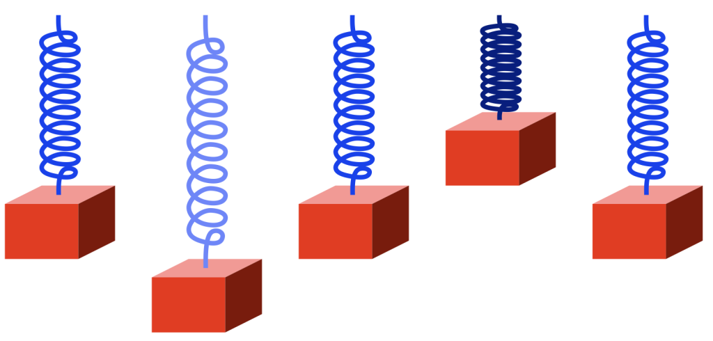
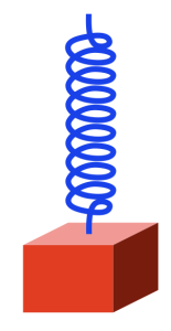
Take a block that’s reasonably heavy and hang it using a spring so that it looks like this:

Figure 1.

The spring is a little stretched because the weight of the block (which is the result of its mass and the Earth’s gravity) is pulling downwards. (We’ll ignore the fact that the spring is also holding up its own weight. Let’s keep this simple…) However, it doesn’t fall to the floor because the spring is pulling upwards.

Now pull downwards on the block, so it will look like the example on the right in the figure below.

Figure 2.

The spring is stretched because we’re pulling down on the block. The spring is also pulling upwards more, since it’s pulling against the weight of the block PLUS the force that you’re adding in a downwards direction.

Now you let go of the block. What happens?

The spring is pulling “too hard” on the block, so the block starts rising back to where it started (we’ll call that the “resting position”). However, when it gets there, it has inertia (a body in motion tends to stay in motion… until it hits something big…) so it doesn’t stop. As a result, it moves upwards, higher than the resting position. This squeezes the spring until it gets to some point, at which time the block stops, and then starts going back downwards. When it returns to the resting position, it still has inertia, so it passes that point and goes too far down again. I’ve shown this as a series of positions from left to right in the figure below.

Figure 3

If there were no friction, no air around the block, and no friction within the metal molecules of the spring, then this would bounce up and down forever.

However, there is friction, so some of the movement (“kinetic energy”) is turned into heat and lost. So, each bounce gets smaller and smaller and the maximum velocity of the block (as it passes the resting position) gets lower and lower, until, eventually, it stops moving (at the resting position, where it started).

Notice that I changed the colour of the spring to show when it’s more stretched (lighter blue) and when it’s more compressed (darker blue).

If everything were behaving perfectly, then the RATE at which the bounce repeats wouldn’t change. Only its amplitude (or the excursion of the block, or the height of the bounce) would reduce over time. That bounce rate (let’s say 1 bounce per second, and by “bounce” I mean a full cycle of moment down, up, and back down to where it started again) is the frequency of the repetition (or oscillation).

If you make the weight lighter, then it will bounce faster (because the spring can pull the weight more “easily”). If you make the spring stiffer, then it will bounce faster (because the spring can pull the weight more “easily”). So, we can change the frequency of the oscillation by changing the weight of the block or the stiffness of the spring.

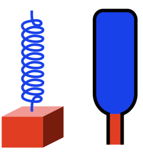
Now take a look at the same weight on a spring next to an up-side down wine bottle that (sadly) has been emptied of wine.

Figure 4.

Notice that I’ve added some colours to the air inside the bottle. The air in the bottle itself is blue, just like the colour of the spring. This is because, if we pull air out of the bottle (downwards), the air inside it will pull back (upwards; just like the metal spring pulling back upwards on the block). I’ve made the small cylinder of air in the neck of the bottle red, just like the block. This is because that air has some mass, and it’s free to move upwards (into the bottle) and downwards (out of the bottle) just like the block.

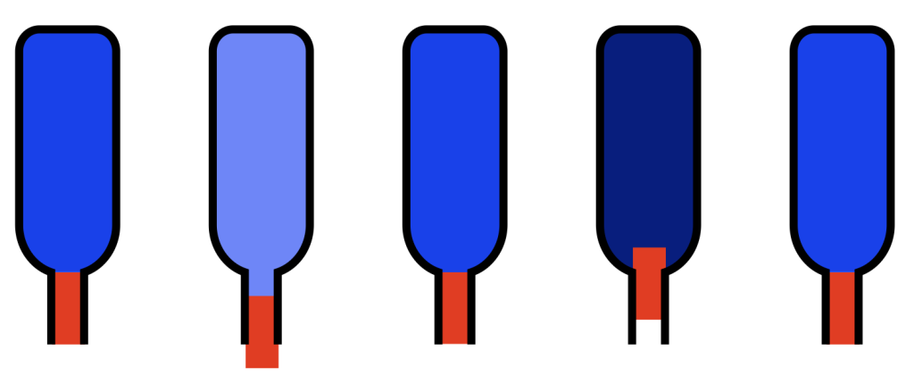
If I were somehow able to pull the “plug” of air out of the neck of the bottle, the air inside would try to pull it back in. If I then “let go”, the plug would move inwards, go too far (because it also has inertia), squeezing (or compressing) the air inside the bottle, which would then push the plug back out. This is shown in the figure below.

Figure 5.

At the level we’re dealing with, this behaviour is practically identical to the behaviour of the block on the spring. In other words, although the block and the plug are made of different materials, and although the metal spring and the air inside the bottle are different materials, Figures 3 and 5 show the same behaviour of the same kind of system.

How do you pull the plug of air out of the bottle? It’s probably easier to start by pushing it inwards instead, by blowing across the top.

When you do this, a little air leaks into the opening, pushing the plug inwards. The “spring” in the bottle then pushes the plug outwards, and your cycle has started. If you wanted to do the same thing with the block, you’d lift it and let go to start the oscillation.

However, you don’t need to blow across the bottle to make it oscillate. You can just tap it with the palm of your hand, for example. Or, if you put the bottle next to your ear and listen carefully, you’ll hear a note “singing along” with the sound in the room. This is because the air in the bottle resonates; it moves back and forth very easily at the frequency that’s determined by the mass of the air in the neck and the volume of air in of the bottle (the spring).

However, remember that friction can make the oscillation decay (or die away) faster, by turning the movement into heat.

One last thing…

There’s another way to get either the block or the wine bottle oscillating:

You can move the TOP of the spring (for example, if you pull it up, then the spring will pull the block upwards, and it’ll start bouncing). Or, you could tap the bottom of the wine bottle (which is on the top in my drawings).

This method of starting the oscillation will come in handy in part 2.

Dynamic Styli Correlator Pt. 5

In the last posting, I showed a scale drawing of a 15 µm radius needle on a 1 kHz sine tone with a modulation velocity of 50 mm/s (peak) on the inside groove of a record. Looking at this, we could see that the maximum angular rotation of the contact point was about 13º away from vertical, so the total range of angular rotation of that point would be about 27º.

I also mentioned that, because vinyl is mastered so that the signal on the groove wall has a constant velocity from about 1 kHz and upwards, then that range will not change for that frequency band. Below 1 kHz, because the mastering is typically ensuring a constant amplitude on the groove wall, then the range decreases with frequency.

We can do the math to find out exactly what the angular rotation the contact point is for a given modulation velocity and groove speed.

Figure 1: A scale drawing of a 15 µm radius needle on a 1 kHz sine tone with a modulation velocity of 50 mm/s (peak) on the inside groove of a record. These two points are the two extremes of the angular rotation of the contact point.

Looking at Figure 1, the rotation is ±13.4º away from vertical on the maximum; so the total range is 26.8º. We convert this to a time modulation by converting that angular range to a distance, and dividing by the groove speed at the location of the needle on the record.

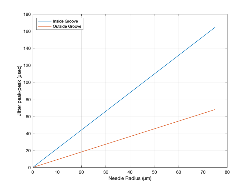
If we repeat that procedure for a range of needle radii from 0 µm to 75 µm for the best-case (the outside groove) and the worst-case (the inside groove), we get the results shown in Figure 2.

Figure 2. The peak-to-peak equivalent “jitter” values of the inside and outside grooves for a range of needle radii.

Dynamic Styli Correlator Pt. 4

Back in Part II of what is turning out to be a series of postings on this topic, I wrote

If this were a digital system instead of an analogue one, we would be describing this as ‘signal-dependent jitter’, since it is a time modulation that is dependent on the slope of the signal. So, when someone complains about jitter as being one of the problems with digital audio, you can remind them that vinyl also suffers from the same basic problem…

As I was walking the dog on another night, I got to thinking whether it would be possible to compare this time distortion to the jitter specifications of a digital audio device. In other words, is it possible to use the same numbers to express both time distortions? That question led me here…

Remember that the effect we’re talking about is caused by the fact that the point of contact between the playback needle and the surface of the vinyl is moving, depending on the radius of the needle’s curvature and the slope of the groove wall modulation. Unless you buy a contact line needle, then you’ll see that the radius of its curvature is specified in µm – typically something between about 5 µm and 15 µm, depending on the pickup.

Now let’s do some math. The information and equations for these calculations can be found here.

We’ll start with a record that is spinning at 33 1/3 RPM. This means that it makes 0.556 revolutions per second.

The Groove Speed relative to the needle is dependent on the rotation speed and the radius – the distance from the centre of the record to the position of the needle. On a 12″ LP, the groove speed at the outside groove where the record starts is 509.8 mm/sec. At the inside groove at the end of the record, it’s 210.6 mm/sec.

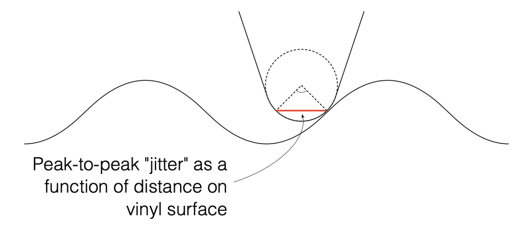
Let’s assume that the angular rotation of the contact point (shown in Figure 1) is 90º. This is not based on any sense of scale – I just picked a nice number.

Figure 1. Artists rendition of the range of the point of contact between the surface of the vinyl and the pickup needle.

We can convert that angular shift into a shift in distance on the surface of the vinyl by finding the distance between the two points on the surface, as shown below in Figure 2. Since you might want to choose an angular rotation that is not 90º, you can do this with the following equation:

2 * sin(AngularRotation / 2) * radius

So, for example, for a needle with a radius of 10 µm and a total angular rotation of 90º, the distance will be:

2 * sin(90/2) * 10 = 14.1 µm

Figure 2. The angular range from Figure 1 converted to a linear distance on the vinyl’s surface.

We can then convert the “jitter” as a distance to a jitter in time by dividing it by the distance travelled by the needle each second – the groove speed in µm per second. Since that groove speed is dependent on where the needle is on the record, we’ll calculate it as best-case and a worst-case values: at the outside and the inside of the record.

Jitter Distance / Groove Speed = Jitter in time

For example, at the inside of the record where the jitter is worst (because the wavelength is shortest and therefore the maximum slope is highest), the groove speed is about 210.6 mm/sec or 210600 µm/sec.

Then the question is “what kind of jitter distance should we really expect?”

Figure 3. Scale drawing of a needle on a record.

Looking at Figure 3 which shows a scale drawing of a 15 µm radius needle on a 1 kHz tone with a modulation velocity of 50 mm/s (peak) on the inside groove of a record, we can see that the angular rotation at the highest (negative) slope is about 13.4º. This makes the total range about 27º, and therefore the jitter distance is about 7.0 µm.

If we have a 27º angular rotation on a 15 µm radius needle, then the jitter will be

7.0 / 210600 = 0.0000332 or 33.2 µsec peak-to-peak

Of course, as the radius of the needle decreases, the angular rotation also decreases, and therefore the amount of “jitter” drops. When the radius = 0, then the jitter = 0.

It’s also important to note that the jitter will be less at the outside groove of the record, since the wavelength is longer, and therefore the slope of the groove is lower, which also reduces the angular rotation of the contact point.

Since the groove on records are typically equalised to ensure that you have a (roughly) constant velocity above 1 kHz and a constant amplitude below, then this means that the maximum slope of the signal and therefore the range of angular rotation of the contact point will be (roughly) the same from 1 kHz to 20 kHz. As the frequency of the signal descended from 1 kHz and downwards, the amplitude remains (roughly) the same, so the velocity decreases, and therefore the range of the angular rotation of the contact point does as well.

In other words, the amount of jitter is 0 at 0 Hz, and increases with frequency until about 1 kHz, then it remains the same up to 20 kHz.

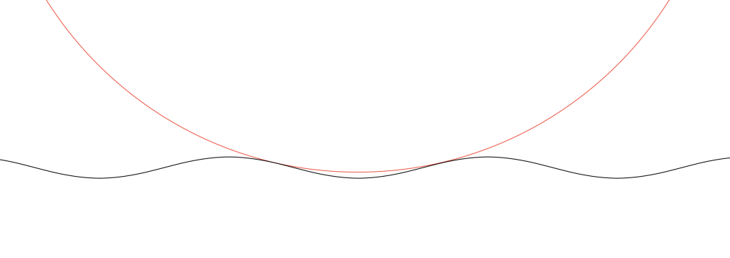
As one final thing: as I was drawing Figure 3, I also did a scale drawing of a 20 kHz signal with the same 50 mm/s modulation velocity and the same 15 µm radius needle. It’s shown in Figure 4.

Figure 4. Scale drawing of a needle on a record.

As you can see there, the needle’s 15 µm radius means that it can’t drop into the trough of the signal. So, that needle is far too big to play a CD-4 quad record (which can go all the way up to 45 kHz).

Dynamic Styli Correlator Pt. 3

I thought that I was finished talking about (and even thinking about) the RCA Dynagroove Dynamic Styli Correlator as well as tracking and tracing distortion… and then I got an email about the last two postings pointing out that I didn’t mention two-channel stereo vinyl, and whether there was something to think about there.

My first reaction was: “There’s nothing interesting about that. It’s just two channels with the same problem, and since (at least in a hypothetical world) the two axes of movement of the needle are orthogonal, then it doesn’t matter. It’ll be the same problem in both channels. End of discussion.”

Then I took the dog out for a walk, and, as often happens when I’m walking the dog, I re-think thoughts and come home with the opposite opinion.

So, by the time I got home, I realised that there actually is something interesting about that after all.

Starting with Emil Berliner, record discs (original lacquer, then vinyl) have been cut so that the “mono” signal (when the two channels are identical) causes the needle to move laterally instead of vertically. This was originally (ostensibly) to isolate the needle’s movement from vibrations caused by footsteps (the reality is that it was probably a clever manoeuvring around Edison’s patent).

This meant that, when records started supporting two audio channels, a lateral movement was necessary to keep things backwards-compatible.

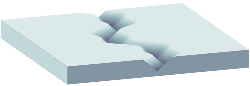
What does THIS mean? It means that, when the two channels have the same signal (say, on the lead vocal of a pop tune, for example) when the groove of the left wall goes up, the groove of the right wall goes down by the same amount. That causes the needle to move sideways, as shown below in Figure 1.

Figure 1. A two-channel groove with identical information in the two channels.

What are the implications of this on tracing distortion? Remember from the previous posting that the error in the movement of the needle is different on a positive slope (where the needle is moving upwards) than a negative slope (downwards). This can be seen in a one-channel representation in Figure 2.

Figure 2. The grey line is the groove wall. The blue line shows the actual movement of the needle and the red line shows the difference between the two – the error contained in the output signal.

Since the two groove walls have an opposite polarity when the audio signals are the same, then the resulting movement of the two channels with the same magnitude of error will look like Figure 3.

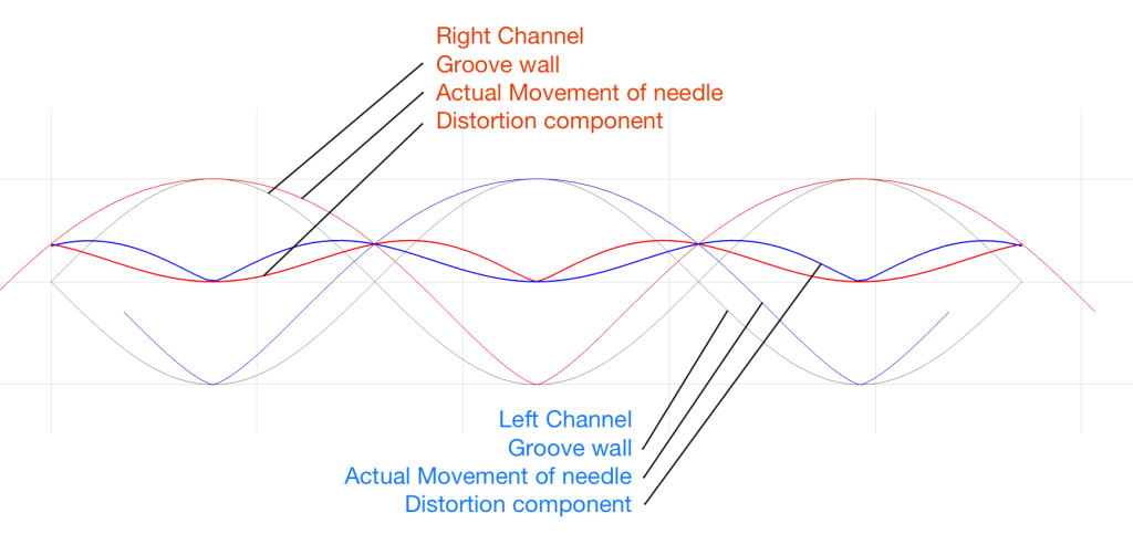
Figure 3. The physical movement of the two channels, and their independent errors.

Notice that, because the two groove walls are moving in opposite polarity (in other words, one is going up while the other is going down) this causes the two error signals to shift by 1/2 of a period.

However, Figure 3 doesn’t show the audio’s electrical signals. It shows the physical movement of the needle. In order to show the audio signals, we have to flip the polarity of one of the two channels (which, in a real pickup would be done electrically). That means that the audio signals will look like Figure 4.
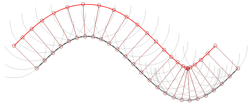
Figure 4. The electrical outputs of the two audio channels and their error components.

Notice in Figure 4 that the original signals are identical (that’s why it looks like there’s only one sine wave) but their actual outputs are different because their error components are different.

But here’s the cool thing:

One way to think of the actual output signals is to consider each one as the sum of the original signal and the error signal. Since (for a mono signal like a lead vocal) their original signals are identical, then, if you sit in the right place with a properly configured pair of loudspeakers (or a decent pair of headphones) then you’ll hear that part of the signal as a phantom image in the middle. However, since the error signals are NOT correlated, they will not be localised in the middle with the voice. They’ll move to the sides. They’re not negatively correlated, so they won’t sound “phase-y” but they’re not correlated either, so they won’t be in the same place as the original signal.

So, although the distortion exists (albeit not NEARLY on the scale that I’ve drawn here…) it could be argued that the problem is attenuated by the fact that you’ll localise it in a different place than the signal.

Of course, if the signal is only in one channel (like Aretha Franklin’s backup singers in “Chain of Fools” for example) then this localisation difference will not help. Sorry.

Dynamic Styli Correlator Pt. 2

After writing the previous posting, I couldn’t stop thinking about it. Mostly, I wanted to get a better idea of the shape of the waveform that results from the difference in a groove cut with a stylus and a spherically-tipped needle on a turntable pickup. To be perfectly honest, I’m not even interested in a ‘real’ simulation. I just wanted to get an intuitive idea of what’s happening down at that nearly-microscopic level. So, I used Matlab to draw some pictures.

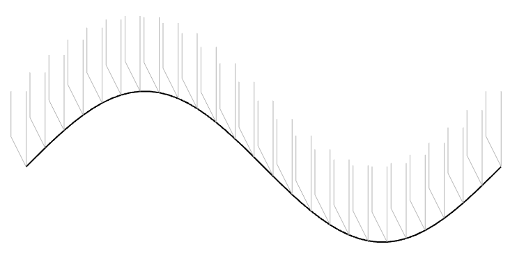
Let’s take one period of a sine wave cut into the vinyl master with a chisel-shaped stylus:

Figure 1: The black line shows the wave cut into the vinyl surface. The grey shapes are “artist’s renditions” of the chisel-shaped stylus that cut it.

In theory, the pickup needle tracks this vertical movement exactly, as shown in Figure 2.

Figure 2. The black line is the original signal. The Red line is the signal tracked by a needle that has the same shape as the cutting stylus.

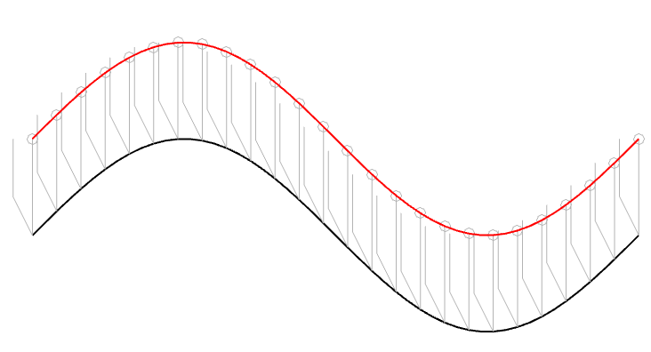
However, we already know that the pickup needle is NOT the same shape as the cutting stylus. In 1964, the needle would have had a spherical tip, which I’ve shown in Figure 3 as a series of semicircles (certainly NOT to scale…).

Figure 3: The black line is the original signal. The grey semicircles are the outline of a spherically-tipped pickup needle. The small grey circles are the centres of those semicircles. When you connect those circles, you get the red line.

In Figure 3, I’ve connected the centres of the semicircles to make the red line. However, you may notice that this line is not directly above the black line because of the interaction between the slope of the original signal and the radius of the ‘sphere’ that I’m showing. This might be easier to see in Figure 4 which is the same as Figure 3, but I’ve ‘connected the dots’.

Figure 4. This is the same as Figure 3, but I’ve shown the radii of the ‘spheres’ connecting the centre to the surface where it’s touching the vinyl.

(1) One interesting thing about the figure above is that it shows that the point where the needle is resting on the vinyl surface isn’t always vertical – it’s 90º from the tangent of the groove wall (assuming a spherically-ground needle). This means that the output of the needle (which, we assume is determined only by its vertical movement) is actually sliding forwards and backwards in time on the recording, depending on whether the slope is positive or negative.

For example, if you look at the far left of Figure 4, you can see that the centre of the needle is to the left of the point where it’s touching the vinyl. If this is drawn so that the vinyl is moving from right to left (or the needle is moving from left to right – so it’s drawn from the perspective of someone looking in from the edge of the record) then this means that the output of the system is looking ahead in time.

When the needle drops back downwards, it’s delaying the signal, looking back in time.

If this were a digital system instead of an analogue one, we would be describing this as ‘signal-dependent jitter’, since it is a time modulation that is dependent on the slope of the signal. So, when someone complains about jitter as being one of the problems with digital audio, you can remind them that vinyl also suffers from the same basic problem…

(2) Another interesting thing is that, if we subtract the original signal on the vinyl’s surface from the actual path traced by the needle, we can see the tracing error itself. This is shown below as the red curve in Figure 5.

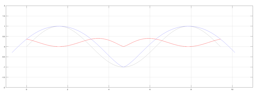
Figure 5. The original signal is in grey, the movement of the needle is in blue, and the difference (the tracing error) is in red.

Notice that, although the original signal is symmetrical, the blue curve (the actual signal) is not. This means that it has a DC offset, which is easily seen in the error curve in red, which never drops below the vertical 0 line; the mean of the original signal.

(Remember, I’m exaggerating everything here just to get an intuitive understanding of what’s going on.)

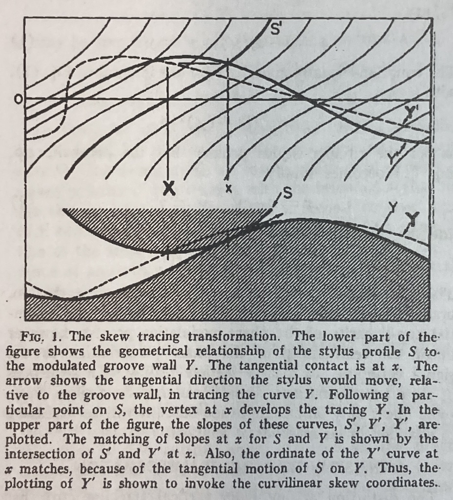
Although I’ve done all of this analysis numerically using Matlab, I’ve also found a paper that describes this error analytically. It’s “Integrated Treatment of Tracing and Tracking Error” by Duane H. Cooper in the Journal of the Audio Engineering Society from January, 1964. In that paper, he shows the following drawing shown below in Figure 6. Compare the dotted line to the blue one above, for example. (It seems that I wasted my time doing math when I should have been reading old papers instead…)

Figure 6.

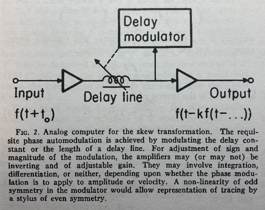
The horizontal distance in Figure 6 between the bold capital ‘X’ and the small ‘x’ is an angular rotation from the centre of the needle’s spherical tip and therefore a time shift in the playback of the recording. Later in the same paper, Cooper proposes an analogue computer that can predict this distortion by modulating a delay applied to the audio signal as a function of the signal itself. A representation of this from the paper is shown below in Figure 7. This prediction can then be used to generate the pre-emphasis distortion of RCA’s “Dynamic Styli Correlator”.

Figure 7.

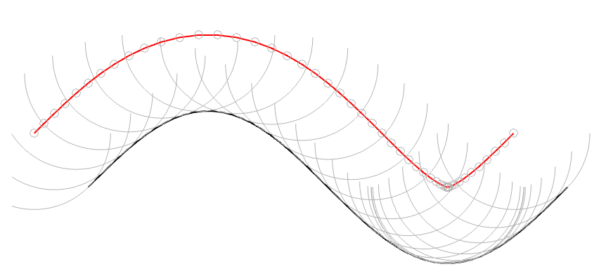
(3) The last thing that I’ve found is an extreme case that should never happen in real life, but it might. This is when the trough that the needle is dropping into is narrower than the diameter of the stylus. When this happens, the point where the stylus is touching jumps instantaneously from one side of the trough to the other. This is shown in Figure 8.

Figure 8. When the stylus is too big to fit into the trough, parts of the waveform are skipped.

This is the same thing that happens when a tire of your car drops into a bad pothole. You roll off one edge of the hole, and hit the edge on the opposite side, but the part of the tire that is actually IN the pothole never actually touches the bottom.

This problem is the same as I described above; but instead of the output signal merely sliding in time, it’s jumping. One example I can think where this would happen in real life is when you play a CD-4 quad LP with a needle that isn’t made for it. However, in this case you won’t notice the problem, since the high-frequency FM modulated surround channels result in a more-or-less constant “ripple” on the groove wall. This means that your needle is just surfing along the tops of the ripples and never drops into a trough at all.

Dynamic Styli Correlator Pt. 1

Many audio recording systems are based on a concept known as “pre-emphasis” and “de-emphasis”. This is a process where a signal is distorted (here, I use the word “distorted” to mean “changed”, not “clipped”) at the recording or encoding process to counter-act the effects of something that will happen at playback. One example of this is a RIAA equalisation that applies an overall bass-heavy tilt to the frequency response at playback, and therefore the signal is given the opposite tilt when it’s cut onto the vinyl master. Dolby noise reduction for analogue magnetic tape follows a similar philosophy.

Another type of intentional distortion applied to an audio signal is based on assumptions of what happens at playback. Mixing engineers for television often emphasise lower frequency bands, assuming that everyone’s television loudspeakers needed some help. Pop and rock recording engineers check the mix on a low-quality mono loudspeaker and may make adjustments to the mix – to make sure it survived a clock radio or a portable Bluetooth loudspeaker (depending on which decade we’re talking about). Stereo vinyl records can’t have big low-frequency differences in the two audio channels otherwise the needle will hop out of the groove, so they’re mixed and mastered accordingly.

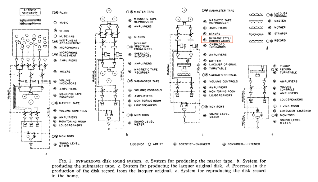
I’ve been reading “The RCA Victor Dynagroove System”, by Harry F. Olsen, published in the April 1964 issue of the Journal of the Audio Engineering Society. In it, he describes the entire recoding chain, including something that piqued my interest called a “Dynamic Styli Correlator” which is a distortion that is applied to the audio at almost the last stage of the signal path before it reaches the cutter head of the lathe that creates the lacquer master. You can see it here in Figure 1 from the article (I drew the red box around it).

Cool name; almost worthy of Dr. Heinz Doofenshmirtz (although it’s missing the “-inator”). But what is it?

One of the problems with playing back a vinyl record is that the shape of the needle on your turntable is not the same shape as the cutting stylus on the lathe. Consequently, the path that the needle tracks is not exactly the same as the path of the stylus. The result of this mis-match is that the electrical input signal that is used to make the master (the original recording) is not the same as the electrical output signal that comes out of your turntable (what you hear).

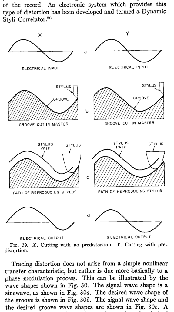
The idea behind the Dynamic Styli Correlator was that the actual path of the playback needle could be predicted, and the groove cut by the stylus could be modified to ensure that the output was correct. In other words, the distortion caused by the playback needle was estimated, and a distorted groove was cut to make the needle behave. This is shown graphically in Figure 29 of the article:

This is a great idea if the system works and if the prediction of the playback needle’s path is correctly predicted. However, neither of these two assumptions is guaranteed; so a number of things can go wrong here, and if anything can go wrong, it probably will.

However, it does mean at least as a start, that if you play an old RCA Victor Dynagroove record with a stylus shape that wasn’t invented yet in 1964 (say, a contact line stylus made for CD-4 Quadraphonic records, for example). Then you might wind up doing a much better job of reproducing the distortion that RCA created in the first place, instead of what they thought you were supposed to hear.

Internal vs. External Volume Control

#93 in a series of articles about the technology behind Bang & Olufsen

A question came to my desk this week from a customer who would like to connect a third-party streaming device to his Beolab 50s. He plans to use a USB-Audio connection and his question was “Should I control the volume of the audio signal in the streamer or in the Beolab 50s?” There are three different ways to configure these two options:

  1. Control the volume in the streamer using its interface, and send a signal that has been volume-regulated to the Beolab 50s, which should then be set to have a start up default volume such that the maximum volume on the streamer results in a level that is as loud as the customer will ever want it to be. In order to do this, the Beolab 50s need to be set to ignore the volume information that is received on the USB-Audio connection.
  2. Set the streamer to output an unregulated signal, and set the Beolab 50s to obey the volume information that is received on the USB-Audio connection, then use the streamer’s interface for the volume control (which would actually be happening inside the Beolab 50s).
  3. Set the streamer to output an unregulated signal, and set the Beolab 50s to disobey the volume information that is received on the USB-Audio connection, then use the Beolab 50’s interface for the volume control (which would actually be happening inside the Beolab 50s).

Of course, one way to answer the question is “where do you want to control the volume?” For example, if it’s with a remote control for the Beolab 50s, then the answer is “use option #3”. If you’d prefer to use the streamer’s app, for example, then the answer is “use option #1 or #2”.

However, the question came to my desk because it was specifically about the technical performance of the audio signal. Which of these three options results in the highest audio “quality”? (I put the word “quality” in quotation marks because it is a loaded term, and might mean different things to different persons…)

The simplest answer without getting into any details is “it probably doesn’t matter“. However, that answer is based on a couple of assumptions that may or may not be wrong.

Hypothetically, the Beolab 50 can output an audio signal that peaks at about 122 dB SPL measured at 1 m in a free field, albeit not at all frequencies present at its output. (This is because there are some physical limitations of how far the woofers can move, which means that you can’t get 122 dB SPL at 20 Hz, for example.) The noise floor of the Beolab 50s is about 0 dB SPL measured in the same place (again, this is frequency-dependent). So, it has a total dynamic range at its output of about 122 dB.

The maximum output level is a result of a combination of the loudspeaker drivers, the amplifiers, and the power supply, however, these have all been chosen to reach their maximum outputs approximately simultaneously, so changing one of the three won’t make a big difference.

The noise floor is a result of the combination of the loudspeaker drivers’ sensitivities, the amplifiers’ noise floors, and the signal that feeds the amplifiers: the DAC outputs’ noise floors. For the purposes of this discussion, I’m sticking with a digital input, so we don’t need to worry about the noise floor of the ADC at the loudspeaker’s input.

If you have an audio signal at one of the digital inputs of the Beolab 50, and that signal is at its loudest possible level (for a sine wave, that’s 0 dB FS; or 0 dB relative to Full Scale). At Beolab 50’s maximum volume setting, this will produce a peak output level of 122 dB SPL (depending on the frequency as I mentioned above).

All digital inputs of the Beolab 50 accept at least a 24 bit word length. This means that the dynamic range of the digital input signal itself is about 6 * 24 – 3 = 141 dB. This in turn means that the hypothetical noise floor of a correctly-dithered 24-bit signal is 19 dB below the noise floor of the loudspeakers even at their maximum volume setting. (because 122 – 141 = -19)

In other words, if we assume that the streamer has a correctly-implemented gain function for its volume control, using TPDF dither implemented at the 24-bit level, then its noise floor will be 19 dB below the “natural” noise floor of the Beolab 50. Therefore, if the volume is controlled in the streamer, any artefacts will be masked by the 50s themselves.

On the other hand, the Beolab 50s volume control is done using a gain function that is performed in a 32-bit floating point calculation, which means that it has a dynamic range of 144 to 150 dB. (See this posting for an explanation and comparison of fixed point and floating point systems.) So the noise generated by the internal volume control will be somewhere between 22 and 26 dB below the “natural” noise floor of the Beolab 50.

So, (assuming my assumptions are correct) the noise floor that is produced by controlling the volume control in either the streamer or the Beolab 50s is FAR below the constant noise floor of the DAC / amplifiers.

In addition, the noise floors have roughly the same spectra (in other words, you don’t have pink noise in one case but white noise in the other; they’re all producing white noise). And since both are so far below, it really doesn’t matter. Arguing about whether the noise is 19 dB lower or 22 dB lower is a waste of good argument time, unless you paid for the four-and-a-half-hour argument instead of the five-minute one…

Important Notes

If the customer was asking about using the analogue input, then the answer MIGHT have been different.

Also, if my assumption about a 24-bit signal coming from the streamer, or that it has a correctly-implemented gain function for its volume control are incorrect, the this answer MIGHT be incorrect as well.

Data sonification

Back when I was at McGill, one of my fellow Ph.D. students was Mark Ballora, who did his doctorate in converting heart rate data to an audible signal that helped doctors to easily diagnose patients suffering from sleep apnea.

This article from Science magazine in 2017 talked about Mark’s later work sonifying astronomical data, but I was reminded of it in a recent article on the BBC about researchers doing the same kind of work.